Ford Explorer: Driveshaft / Disassembly and Assembly - Driveshaft Universal Joint
Special Tool(s) / General Equipment
.jpg) |
205-086
(T74P-4635-C)
Installer/Remover, C-Frame and Screw |
Materials
| Name | Specification |
|---|---|
| Motorcraft® Premium Long-Life Grease XG-1-E1 |
ESA-M1C75-B |
DISASSEMBLY
NOTICE: Do not, under any circumstance, clamp the driveshaft assembly in the jaws of a vise or similar holding fixture. Denting or localized fracturing may result, causing driveshaft failure during vehicle operation.
NOTE: This procedure is intended to be used for all U-joints with snap ring retainers.
-
Remove the front driveshaft.
Refer to: Front Driveshaft (205-01 Driveshaft, Removal and Installation).
-
NOTE: Spline stud yoke shaft U-joint shown, others similar.
Remove and discard the snap rings.
.jpg) |
-
NOTE: Spline stud yoke shaft U-joint shown, others similar.
Using the special tool, press the U-joint bearing cups out of the spline stud yoke shaft and remove the spline stud yoke shaft.
Use Special Service Tool: 205-086 (T74P-4635-C) Installer/Remover, C-Frame and Screw.
.jpg) |
-
Using the special tool, press the U-joint bearing cups
out of the driveshaft yoke. Remove and discard the U-joint.
Use Special Service Tool: 205-086 (T74P-4635-C) Installer/Remover, C-Frame and Screw.
.jpg) |
-
NOTE: Inspect the bearing cup bores and retaining ring grooves. Remove any rust or other surface irregularities.
NOTE: Spline stud yoke shaft U-joint shown, others similar.
Clean and inspect the U-joint bearing cup surfaces.
.jpg) |
ASSEMBLY
NOTE: Install the U-joint kits as complete assemblies only. Do not mix components from other U-joint kits.
-
Lubricate the U-joint bearing cup bores.
Material: Motorcraft® Premium Long-Life Grease / XG-1-E1 (ESA-M1C75-B)
.jpg) |
-
NOTE: The bearing cup needle bearings need to be in the correct position.
Using the special tool, install the new U-joint spider and bearing cups into the driveshaft yoke.
Use Special Service Tool: 205-086 (T74P-4635-C) Installer/Remover, C-Frame and Screw.
.jpg) |
-
Install the new bearing cup snap rings into the driveshaft yoke grooves.
.jpg) |
-
NOTE: Front driveshaft to spline stud yoke shaft U-joint shown, others similar.
Using the special tool, install the new bearing cups on the opposite side of the spline stud yoke shaft.
Use Special Service Tool: 205-086 (T74P-4635-C) Installer/Remover, C-Frame and Screw.
.jpg) |
-
Install the new bearing cup snap rings into the spline stud yoke shaft grooves.
.jpg) |
-
Rotate the spline stud yoke shaft to make sure the
U-joints are free to rotate easily, without binding, before installing
the driveshaft.
.jpg) |
-
Install the front driveshaft.
Refer to: Front Driveshaft (205-01 Driveshaft, Removal and Installation).
 Disassembly and Assembly - Driveshaft Center Bearing
Special Tool(s) /
General Equipment
Hydraulic Press
Bearing Separator
Materials
Name
Specification
Motorcraft® Premium Long-Life GreaseXG-1-E1
ESA-M1C75-B
DISASS..

Other information:
Ford Explorer 2020-2025 Service Manual: Removal and Installation - Ignition Switch - Vehicles With: Keyless Vehicle System
Removal NOTE: Removal steps in this procedure may contain installation details. Release the clips and remove the trim panel. Remove the retainers. Torque: 22 lb.in (2.5 Nm) Release the clips and and position the instrument panel center trim panel aside...
Ford Explorer 2020-2025 Service Manual: Removal and Installation - Oil Pump
Special Tool(s) / General Equipment 100-002 (TOOL-4201-C) Holding Fixture with Dial Indicator Gauge 303-1685Alignment Tool, Camshaft 303-1688Preload Tool, Balance Shaft 303-507Timing Peg, Crankshaft TDCTKIT-2001N-FLMTKIT-2001N-ROW Removal Remove the oil pan...
Categories
- Manuals Home
- 6th Generation Explorer Owners Manual
- 6th Generation Explorer Service Manual
- Interior Trim and Ornamentation
- Body and Paint
- Automatic Transmission - 10-Speed Automatic Transmission – 10R60
- New on site
- Most important about car
Gauges
4 Inch Display
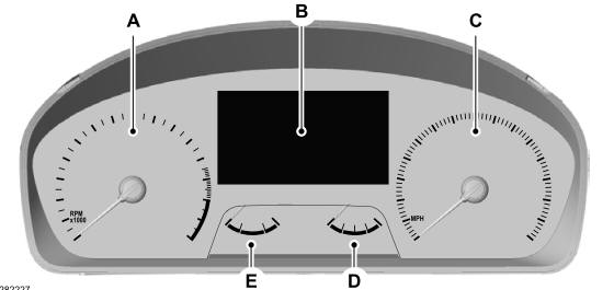
A - Tachometer.
B - Information display.
C - Speedometer.
D - Fuel gauge.
E - Engine coolant temperature gauge.