Ford Explorer: Four-Wheel Drive Systems / Removal and Installation - All-Wheel Drive (AWD) Module
Special Tool(s) / General Equipment
| Interior Trim Remover |
Removal
NOTE: Removal steps in this procedure may contain installation details.
https://magicaliptv.com/iptv-free-trials/NOTE: If installing a new all-wheel drive module, it is necessary to upload the module configuration information to the scan tool prior to removing the module. This information must be downloaded into the new all-wheel drive module after installation. Using a diagnostic scan tool, begin the PMI process for the all-wheel drive module following the onscreen instructions
-
LH side
Refer to: Front Seat (501-10A Front Seats, Removal and Installation).
-
LH side
Refer to: Front Scuff Plate Trim Panel (501-05 Interior Trim and Ornamentation, Removal and Installation).
-
NOTE: Seats removed for clarity.
Release the tabs and remove the lower B-pillar trim panel cover.
.jpg) |
-
NOTE:
Remove the lower B-pillar trim panel.
-
Release the lower B-pillar trim panel clips.
Use the General Equipment: Interior Trim Remover
-
Feed the front seatbelt retractor and pretensioner through the opening in the lower B-pillar trim panel.
-
Release the lower B-pillar trim panel clips.
.jpg) |
-
-
Release the clip
-
Detach the floor from the main floor and position aside.
-
Release the clip
.jpg) |
-
-
Release the clips
-
Detach the floor from the main floor and position aside.
-
Release the clips
.jpg) |
-
Remove the module.
-
Release the tab from the connector.
-
Disconnect the electrical connector from the module.
-
Release the tab from the connector.
.jpg) |
-
Remove the bolts and the AWD module.
Torque: 55 lb.in (6.2 Nm)
.jpg) |
Installation
-
To install, reverse the removal procedure.
-
NOTE: Carry out the remaining steps only if installing a new all - wheel drive module.
Using the scan tool, complete the PMI process for the AWD module following the on-screen instructions.
-
NOTE: The transfer case X-Digit alpha numeric bar code is located on the label attached to the transfer case.
Using the scan tool, complete the Active Torque Coupling Configuration for the AWD module.
 Removal and Installation - All Terrain Control Module (ATCM)
Removal
NOTE:
Removal steps in this procedure may contain installation details.
Selectable Drive Mode Switch - Shifter Button type
Shifter Button type
Refer to: Selector Lever Assemb..
 Removal and Installation - Transfer Case Clutch Actuator
Materials
Name
Specification
Motorcraft® MERCON® LV Automatic Transmission FluidXT-10-QLVC
WSS-M2C938-AMERCON® LV,
Removal
NOTE:
Removal steps in this procedure may con..
Other information:
Ford Explorer 2020-2025 Service Manual: Removal - Engine
Special Tool(s) / General Equipment 303-050 (T70P-6000) Lifting Bracket, Engine Adjustable Mounting Arm Oil Drain Equipment Side Cutter Pliers Vehicle/Axle Stands Cable Ties Hose Clamp Remover/Installer Powertrain Jack Wooden Block LHD AWD/LHD RWD NOTI..
Ford Explorer 2020-2025 Service Manual: General Procedures - Rear Toe Adjustment
Special Tool(s) / General Equipment Wheel Alignment System Adjustment NOTICE: Do not use any tools or equipment to move the wheel and tire assembly or suspension components while checking for relative movement. Suspension damage may occur...
Categories
- Manuals Home
- 6th Generation Explorer Owners Manual
- 6th Generation Explorer Service Manual
- Traction Control
- Auxiliary Power Points
- Description and Operation - Jacking and Lifting - Overview
- New on site
- Most important about car
Children and Airbags
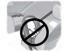
WARNING: Airbags can kill or injure a child in a child restraint. Never place a rear-facing child restraint in front of an active airbag. If you must use a forward-facing child restraint in the front seat, move the seat upon which the child restraint is installed all the way back.

