Ford Explorer: Exhaust System - 2.3L EcoBoost (201kW/273PS) / Removal and Installation - Catalytic Converter
Ford Explorer 2020-2025 Service Manual / Powertrain / Exhaust System / Exhaust System - 2.3L EcoBoost (201kW/273PS) / Removal and Installation - Catalytic Converter
Removal
.jpg) WARNING:
When the engine and exhaust system are hot, they can cause
severe burns or injury. Turn off the engine and wait until they are cool
before removing the exhaust system.
WARNING:
When the engine and exhaust system are hot, they can cause
severe burns or injury. Turn off the engine and wait until they are cool
before removing the exhaust system.
NOTE: Removal steps in this procedure may contain installation details.
All vehicles
-
Refer to: Health and Safety Precautions (100-00 General Information, Description and Operation).
-
Remove the HO2S from the catalytic converter.
Refer to: Heated Oxygen Sensor (HO2S) (303-14A Electronic Engine Controls - 2.3L EcoBoost (201kW/273PS), Removal and Installation).
-
With the vehicle in NEUTRAL, position it on a hoist.
Refer to: Jacking and Lifting - Overview (100-02 Jacking and Lifting, Description and Operation).
-
Remove the muffler inlet pipe assembly.
Refer to: Muffler Inlet Pipe (309-00 Exhaust System - 2.3L EcoBoost (201kW/273PS)) .
-
Remove the catalyst monitor sensor.
Refer to: Catalyst Monitor Sensor (303-14A Electronic Engine Controls - 2.3L EcoBoost (201kW/273PS), Removal and Installation).
4x4 vehicles
-
Remove the front Driveshaft.
Refer to: Front Driveshaft (205-01 Driveshaft, Removal and Installation).
All vehicles
-
Remove and discard the catalytic converter to turbocharger nuts.
.jpg) |
-
-
Remove the PIA nuts.
-
Remove the bracket nuts. Remove the bracket and the catalytic converter.
-
Remove the PIA nuts.
.jpg) |
-
Remove and discard the gasket.
.jpg) |
Installation
All vehicles
-
Clean all exhaust connections before reassembly.
-
-
Clean and inspect the gasket surface and the studs. Replace the studs if necessary.
Torque: 18 lb.ft (25 Nm)
-
NOTE: Make sure that a new gasket is installed.
Install a new gasket.
-
Clean and inspect the gasket surface and the studs. Replace the studs if necessary.
.jpg) |
-
NOTE: The nuts are only finger tight in this step.
Install the catalytic converter. Install the mounting bracket and the nuts.
|
-
NOTE: Make sure that new nuts are installed.
Install the catalytic converter nuts.
Torque: 35 lb.ft (47.5 Nm)
.jpg) |
-
-
Tighten the nuts.
Torque: 18 lb.ft (25 Nm)
-
Tighten the PIA nuts.
Torque: 18 lb.ft (25 Nm)
-
Tighten the nuts.
.jpg) |
4x4 vehicles
-
Install the front Driveshaft.
Refer to: Front Driveshaft (205-01 Driveshaft, Removal and Installation).
All vehicles
-
To install, reverse the removal procedure.
-
Check the exhaust system for leaks.
 Diagnosis and Testing - Exhaust System
Symptom Chart(s)
Symptom Chart: Symptom Chart - Exhaust System
Verify
the customer concern. Inspect the components of the exhaust system for
obvious signs of damage or other mechanical concern..
 Removal and Installation - Downstream Catalytic Converter
Removal
NOTE:
Removal steps in this procedure may contain installation details.
Refer to: Health and Safety Precautions (100-00 General Information, Description and Operation)...
Other information:
Ford Explorer 2020-2025 Service Manual: Removal and Installation - Occupant Classification System (OCS) Sensor - Vehicles With: Multi-Contour Seats
Special Tool(s) / General Equipment Flat Headed Screw Driver Removal WARNING: The following procedure prescribes critical repair steps required for correct restraint system operation during a crash. Follow all notes and steps carefully...
Ford Explorer 2020-2025 Owners Manual: Keyless Starting
Note: The system may not function if the intelligent access key is close to metal objects or electronic devices, for example keys or a cell phone. Note: A valid intelligent access key must be located inside your vehicle to switch the ignition on and start your vehicle...
Categories
- Manuals Home
- 6th Generation Explorer Owners Manual
- 6th Generation Explorer Service Manual
- Removal and Installation - Front Halfshaft Speed Sensor
- Fuel Filler Funnel Location & Running Out of Fuel
- General Procedures - Brake Service Mode Activation and Deactivation
- New on site
- Most important about car
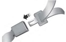
Fastening the Seatbelts
The front outboard and rear safety restraints in the vehicle are combination lap and shoulder belts.
Copyright © 2025 www.foexplorer.com