Ford Explorer: Bumpers / Removal and Installation - Rear Bumper
Ford Explorer 2020-2025 Service Manual / Body and Paint / Body and Paint / Bumpers / Removal and Installation - Rear Bumper
Removal
NOTE: Removal steps in this procedure may contain installation details.
All vehicles
-
Remove the rear bumper cover.
Refer to: Rear Bumper Cover (501-19 Bumpers, Removal and Installation).
Vehicles without trailer tow package
-
On both sides.
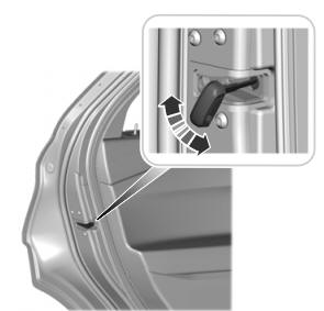
Remove the bolt, relelase the tab and position the exhaust isolator assembly aside.
Torque: 26 lb.ft (35 Nm)
.jpg) |
-
With the help of an assistant.
Remove the bolts and the rear bumper.
Torque: 129 lb.ft (175 Nm)
.jpg) |
Vehicles with trailer tow package
-
On both sides.
Remove the bolt, relelase the tab and position the exhaust isolator assembly aside.
Torque: 26 lb.ft (35 Nm)
.jpg) |
-
Disconnect the trailor tow electrical connector, the retainer and remove the wiring harness.
.jpg) |
-
With the help of an assistant.
Remove the bolts and the rear bumper.
Torque: 129 lb.ft (175 Nm)
.jpg) |
Installation
-
To install, reverse the removal procedure.
 Removal and Installation - Front Bumper Cover
Special Tool(s) /
General Equipment
Interior Trim Remover
Removal
NOTE:
Removal steps in this procedure may contain installation details...
 Removal and Installation - Rear Bumper Cover
Special Tool(s) /
General Equipment
Interior Trim Remover
Removal
NOTE:
Removal steps in this procedure may contain installation details...
Other information:
Ford Explorer 2020-2025 Owners Manual: Seatbelt Reminder
WARNING: The system will only provide protection when you use the seatbelt correctly. This system monitors all seating positions and provides audio and graphic feedback. This lamp illuminates and a warning tone sounds if you do not fasten your seatbelt when you switch the ignition on...
Ford Explorer 2020-2025 Service Manual: Removal and Installation - Roof Opening Panel Glass
Removal NOTE: Removal steps in this procedure may contain installation details. NOTE: This procedure is for the sliding glass panel only. Open the roof opening panel shield. On both sides. Detach the top portion of the roof opening panel blind and fold it down to get access to the roof opening panel glass retainers...
Categories
- Manuals Home
- 6th Generation Explorer Owners Manual
- 6th Generation Explorer Service Manual
- Engine
- Automatic Transmission - 10-Speed Automatic Transmission – 10R60
- Body and Paint
- New on site
- Most important about car
Child Safety Locks
When these locks are set, you cannot open the rear doors from the inside.
A child safety lock is on the rear edge of each rear door. You must set the child safety lock separately on each door.
Left-Hand Side
Copyright © 2025 www.foexplorer.com