Ford Explorer: Front Suspension - RWD / Removal and Installation - Wheel Studs
Ford Explorer 2020-2025 Service Manual / Chassis / Suspension / Front Suspension - RWD / Removal and Installation - Wheel Studs
Special Tool(s) / General Equipment
| Hydraulic Press |
Removal
NOTICE: Suspension fasteners are critical parts that affect performance of vital components and systems. Failure of these fasteners may result in major service expense. Use the same or equivalent parts if replacement is necessary. Do not use a replacement part of lesser quality or substitute design. Tighten fasteners as specified.
-
Remove the wheel bearing and wheel hub.
-
Press the wheel stud from the wheel bearing and wheel hub.
Use the General Equipment: Hydraulic Press
.jpg) |
-
Inspect the wheel bearing and wheel hub for damage. Replace as necessary.
.jpg) |
Installation
-
Press the wheel stud into the wheel bearing and wheel hub.
Use the General Equipment: Hydraulic Press
.jpg) |
-
Install the wheel bearing and wheel hub.
 Removal and Installation - Wheel Knuckle
Special Tool(s) /
General Equipment
204-592Separator, Lower Arm Ball JointTKIT-2006C-FFMFLMTKIT-2006C-LMTKIT-2006C-ROW
Removal
NOTICE:
Suspension fasteners are critical parts that a..
 Disassembly and Assembly - Front Strut and Spring Assembly
Special Tool(s) /
General Equipment
Spring Compressor
Vise
DISASSEMBLY
WARNING:
Do not apply heat or flame to the shock absorber or strut
tube...
Other information:
Ford Explorer 2020-2025 Service Manual: Removal and Installation - Front Parking Aid Sensor
Removal Remove the front bumper cover. Refer to: Front Bumper Cover (501-19 Bumpers, Removal and Installation). Remove the front parking aid sensor. Disconnect the electrical connector. Release the tabs. Remove the sensor...
Ford Explorer 2020-2025 Service Manual: Description and Operation - Collision Warning and Collision Avoidance System - System Operation and Component Description
System Operation ACC With Pre-Collision Assist Item Description 1 ACM 2 RCM 3 CCM 4 IPC 5 BCM 6 GWM 7 ABS module 8 IPMA Network Message Chart Network Input Messages - ACM Broadcast Message Originating Module Message Purpose ..
Categories
- Manuals Home
- 6th Generation Explorer Owners Manual
- 6th Generation Explorer Service Manual
- Using Tether Straps
- General Procedures - Brake Service Mode Activation and Deactivation
- Electric Parking Brake
- New on site
- Most important about car
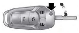
Integrated Keyhead Transmitter (If Equipped)
Use the key blade to start your vehicle and unlock or lock the driver door from outside your vehicle. The integrated keyhead transmitter functions as a programmed ignition key that operates all the locks and starts your vehicle, as well as a remote control.

Copyright © 2025 www.foexplorer.com
