Ford Explorer: Body Repairs - Vehicle Specific Information and Tolerance Checks / Description and Operation - Body and Frame
Body
The body consists of the following:
- Front frame rails constructed of high-strength aluminum
- Rear frame rails constructed of Boron ultra high-strength steel
- Fender reinforcement tube constructed of Dual Phase (DP) 800 high-strength steel
- Cast aluminum fender apron assembly
- Liftgate outer panel constructed of mild steel
- Body structure constructed of Boron, Dual Phase (DP) and high-strength steels
- Roof panel reinforcements constructed of Dual Phase (DP) 600 and mild steel
- Bolted, removable front fenders, hinged doors and hood
- Bodyside outer panels constructed of mild steel
- Steel hood hinges
- Mastic pads used on floor pan for sound deadening
Front End Panel Margining
NOTE: Margining specifications apply to left hand (LH) and right hand (RH) side of the vehicle unless stated.
.jpg)
| Item | Description | Panel Margin Specification | Flush Specification |
| 1 | Hood to Fender | 3.0 mm Maximum: 4.5 mm Minimum: 1.5 mm |
NOTE: Hood under-flush to fender. 0.8 mm Maximum: 2.6 mm Minimum: -1.0 mm |
Side Panel Margining
NOTE: Margining specifications apply to left hand (LH) and right hand (RH) side of the vehicle unless stated.
.jpg)
| Item | Description | Panel Margin Specification | Flush Specification |
| 1 | Fender to Door | 3.4 mm Maximum 4.9 mm Minimum 1.9 mm |
NOTE: Front door under-flush to fender. 0.5 mm Maximum -2.0 mm Minimum 1.0 mm |
| 2 | Door Frame to A-Pillar | 4.5 mm Maximum: 7.2 mm Minimum: 1.8 mm | 2.0 mm Maximum: 4.5 mm Minimum: 1.8 mm |
| 3 | Front and Rear Door to Body Side | 4.5 mm Maximum: 6.5 mm Minimum: 2.5 mm |
NOTE: Door under-flush to body side. 2.0 mm Maximum: 4.5 mm Minimum: -0.5 mm |
| 4 | Front Door Frame to Rear Door Frame | 0.0 mm Maximum: 5.7 mm Minimum: 1.7 mm | 0.0 mm Maximum: 2.7 mm Minimum: -2.7 mm |
| 5 | Front Door to Rear Door | 3.4 mm Maximum: 4.9 mm Minimum: 1.9 mm |
NOTE: Rear door under-flush to front door. -0.5 mm Maximum: 1.5 mm Minimum: -2.5 mm |
| 6 | Rear Door Frame to Quarter Glass | 3.4 mm Maximum: 4.9 mm Minimum: 1.9 mm | 0.0 mm Maximum 1.5 mm Minimum -1.5 mm |
| 7 | Rear Door to Quarter Panel | 3.4 mm Maximum: 4.9 mm Minimum: 1.9 mm | 0.0 mm Maximum: 1.5 mm Minimum: -1.5 mm |
Rear Panel Margining
NOTE: Margining specifications apply to left hand (LH) and right hand (RH) side of the vehicle unless stated.
.jpg)
| Item | Description | Panel Margin Specification | Flush Specification |
| 1 | Liftgate to Tail Lamp | 4.5 mm Maximum: 7.0 mm Minimum: 2.0 mm | - |
| 2 | Liftgate to Rear Bumper Cover | 4.5 mm Maximum: 7.1 mm Minimum: 1.9 mm | - |
| 3 | Liftgate to Quarter Panel | 4.0 mm Maximum: 5.5 mm Minimum: 2.5 mm | - |
| 4 | Spoiler to Quarter Panel | 5.0 mm Maximum 7.2 mm Minimum 2.8 mm | 1.5 mm Maximum: 4.2 mm Minimum: -1.2 mm |
| 5 | Spoiler to Roof | 7.8 mm Maximum: 10.0 mm Minimum: 5.6 mm |
NOTE: Spoiler under-flush to roof. 1.5 mm Maximum: 4.1 mm Minimum: -1.1 mm |
Under Hood Dimensions
NOTE: All dimensions are on center unless otherwise indicted.
.jpg)
Front Structure Dimensions
NOTE: All dimensions are on center unless otherwise indicted.
.jpg)
Front Door Opening Dimensions
NOTE: All dimensions are on center unless otherwise indicted.
.jpg)
Rear Door Opening Dimensions
NOTE: All dimensions are on center unless otherwise indicted.
.jpg)
Lift Gate Opening Dimensions
NOTE: All dimensions are on center unless otherwise indicted.
.jpg)
Under Body Dimensions
NOTE: All dimensions are on center unless otherwise indicted.
.jpg)
Datum Height Dimensions
.jpg)
 Description and Operation - Vehicle Specific Body Construction
For recommended metal repair guidelines and recommendations, refer to the following illustrations and: For additional information, refer to: Specifications (501-25 Body Repairs - General Information, ..
 General Procedures - Body Panel Sectioning
Special Tool(s) /
General Equipment
Resistance Spotwelding Equipment
Spherical Cutter
Air Body Saw
MIG/MAG Welding Equipment
Spot Weld Drill Bit
Locking Pliers
Materia..
Other information:
Ford Explorer 2020-2025 Owners Manual: Engine Block Heater (If Equipped)
WARNING: Failure to follow engine block heater instructions could result in property damage or serious personal injury. WARNING: Do not use your heater with ungrounded electrical systems or two-pronged adapters. There is a risk of electrical shock...
Ford Explorer 2020-2025 Service Manual: General Procedures - Group Flash Pattern Programming
Activation WARNING: Police Package warning lights are a high-intensity Light-Emitting Diode (LED) type. Do not stare directly at these lights, as doing so may cause temporary blindness and/or eye damage. Failure to follow this instruction may result in personal injury...
Categories
- Manuals Home
- 6th Generation Explorer Owners Manual
- 6th Generation Explorer Service Manual
- Engine
- General Procedures - Transmission Fluid Drain and Refill
- Description and Operation - Identification Codes
- New on site
- Most important about car
Child Safety Locks
When these locks are set, you cannot open the rear doors from the inside.
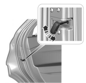
A child safety lock is on the rear edge of each rear door. You must set the child safety lock separately on each door.
Left-Hand Side