Ford Explorer: Automatic Transmission - 10-Speed Automatic Transmission – 10R60 / Description and Operation - C Clutch
Overview
.jpg)
| Item | Description |
| 1 | SSC |
| 2 | C clutch control valve |
| 3 | C clutch latch valve |
| 4 | C clutch apply circuit |
| 5 | C clutch piston |
| 6 | C clutch assembly |
| 7 | Ring gear No. 2 |
| 8 | Shaft (sun gear No. 3) |
| 9 | Sun gear No. 3 |
Ring gear No. 2 is mechanically connected to sun gear No. 3 and is also connected to the C clutch. When the C clutch applies, torque from ring gear No. 2 may be applied the planetary carrier No. 3.
C Clutch Exploded View
.jpg)
| Item | Description |
| 1 | C clutch pressure plate |
| 2 | C clutch steel plates |
| 3 | C clutch friction plates |
| 4 | Ring gear No. 2 |
| 5 | Shaft (sun gear No 3) |
| 6 | C clutch balance dam |
| 7 | C clutch piston return spring |
| 8 | C clutch piston |
| 9 | CDF clutch cylinder |
| 10 | Sun gear No. 3 |
C Clutch Hydraulic Circuits
.jpg)
| Item | Description |
| 1 | Line pressure |
| 2 | Pump output |
| 3 | C clutch control valve |
| 4 | SSC |
| 5 | Control pressure to latch valve |
| 6 | C clutch latch valve |
| 7 | Apply pressure to mechanical C clutch |
| 8 | Mechanical C clutch |
| 9 | Elevated exhaust pressure |
| 10 | Clutch exhaust |
C Clutch Hydraulic Operation
Line pressure is supplied to the C clutch control valve and the C clutch latch valve. As SSC turns on, it moves the control valve allowing regulated line pressure to flow to the C clutch latch valve and then to the mechanical C clutch. When the regulated line pressure in the C clutch control circuit reaches approximately 689 kPa (100 psi), the mechanical C clutch is fully applied. The pressure in the C clutch control circuit moves the C clutch latch valve to the left which allows line pressure to hold the mechanical C clutch applied.
C Clutch Hydraulic Passages
.jpg)
.jpg)
.jpg)
.jpg)
 Description and Operation - B Clutch
Overview
Item
Description
1
SSB
2
B clutch control valve
3
B clutch latch valve
4
B clutch ..
 Description and Operation - D Clutch
Overview
Item
Description
1
SSD
2
D clutch control valve
3
Clutch gain control valve
4
D cl..
Other information:
Ford Explorer 2020-2026 Owners Manual: Illuminated Entry & Illuminated Exit
Illuminated Entry The interior lamps and some exterior lamps illuminate when you unlock the doors with the remote control. The lamps turn off if: The ignition is on. You press the remote control lock button. 25 seconds have elapsed. The lamps do not turn off if: You switch them on with the lighting control...
Ford Explorer 2020-2026 Service Manual: Removal and Installation - Second Row Seat Cushion Blower Motor
Removal NOTE: Removal steps in this procedure may contain installation details. Remove the second row single seat cushion cover. Refer to: Second Row Single Seat Cushion Cover - Vehicles With: Second Row Captain Chairs (501-10B Second Row Seats, Removal and Installation)...
Categories
- Manuals Home
- 6th Generation Explorer Owners Manual
- 6th Generation Explorer Service Manual
- Description and Operation - Identification Codes
- Traction Control
- Using Tether Straps
- New on site
- Most important about car
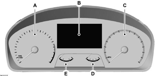
Gauges
4 Inch Display

A - Tachometer.
B - Information display.
C - Speedometer.
D - Fuel gauge.
E - Engine coolant temperature gauge.
