Ford Explorer: Automatic Transmission - 10-Speed Automatic Transmission – 10R60 / Description and Operation - D Clutch
Overview
.jpg)
| Item | Description |
| 1 | SSD |
| 2 | D clutch control valve |
| 3 | Clutch gain control valve |
| 4 | D clutch apply circuit |
| 5 | D clutch piston |
| 6 | D clutch assembly |
| 7 | Planetary carrier No. 3 |
Planetary carrier No. 3 is located in the CDF clutch and planetary carrier assembly. Planetary carrier No. 3 is connected to the D clutch. When the D clutch applies, the planetary carrier No. 3 may be connected to ring gear No. 2.
D Clutch Exploded View
.jpg)
| Item | Description |
| 1 | Planetary carrier No. 3 |
| 2 | D clutch pressure plate |
| 3 | D clutch steel plates |
| 4 | D clutch friction plates |
| 5 | D clutch apply ring |
| 6 | D clutch balance dam |
| 7 | D clutch piston return spring |
| 8 | D clutch piston |
| 9 | CDF clutch cylinder |
D Clutch Hydraulic Circuits
.jpg)
| Item | Description |
| 1 | Line pressure |
| 2 | Pump output |
| 3 | D clutch control valve |
| 4 | SSD |
| 5 | E clutch control valve |
| 6 | SSE |
| 7 | E clutch apply pressure to clutch gain control valve |
| 8 | Clutch gain control valve |
| 9 | LPC solenoid |
| 10 | LPC pressure |
| 11 | D clutch feedback pressure |
| 12 | Apply pressure to mechanical D clutch |
| 13 | Mechanical D clutch |
| 14 | D clutch apply pressure to clutch gain control valve |
| 15 | E clutch feedback pressure |
| 16 | Elevated exhaust pressure |
| 17 | Clutch exhaust |
D Clutch Hydraulic Operation 5th-6th Shift
Line pressure is supplied to the D clutch control valve. LPC pressure is supplied to the gain control valve. LPC pressure positions the gain control valve to the right end of the valve bore. As SSD turns on, it moves the D clutch control valve allowing regulated line pressure to flow to the mechanical D clutch.
D Clutch Hydraulic Operation 2nd-3rd, 4th-5th, and 9th-10th Shifts
Line pressure is supplied to the D clutch control valve. LPC pressure is supplied to the gain control valve. The LPC pressure is low and the gain control valve stays in the default position at the left end of the valve bore. As SSD turns on, it moves the D clutch control valve allowing regulated line pressure to flow to the mechanical D clutch.
D Clutch Hydraulic Passages
.jpg)
.jpg)
.jpg)
.jpg)
 Description and Operation - C Clutch
Overview
Item
Description
1
SSC
2
C clutch control valve
3
C clutch latch valve
4
C clutch ..
 Description and Operation - E Clutch
Overview
Item
Description
1
SSE
2
E clutch control valve
3
Clutch gain control valve
4
E cl..
Other information:
Ford Explorer 2020-2025 Service Manual: Removal and Installation - Hood Latch Release Handle
Removal Remove the hood latch release handle. Rotate the hood latch release handle. NOTE: Do not remove the retaining clip from the hood latch release handle. Release the retaining clip. Remove the hood latch release handle...
Ford Explorer 2020-2025 Service Manual: Diagnosis and Testing - Leakage Inspection
Leak Check Test With the vehicle in NEUTRAL, position it on a hoist. REFER to: Preliminary Inspection (307-01A Automatic Transmission - 10-Speed Automatic Transmission – 10R60, Diagnosis and Testing). Inspect the gasket and sealing areas for evidence of leakage...
Categories
- Manuals Home
- 6th Generation Explorer Owners Manual
- 6th Generation Explorer Service Manual
- Fuel Filler Funnel Location & Running Out of Fuel
- Auxiliary Power Points
- Removal and Installation - Liftgate Trim Panel
- New on site
- Most important about car
Child Safety Locks
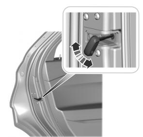
When these locks are set, you cannot open the rear doors from the inside.

A child safety lock is on the rear edge of each rear door. You must set the child safety lock separately on each door.
Left-Hand Side
