Ford Explorer: Automatic Transmission - 10-Speed Automatic Transmission – 10R60 / Diagnosis and Testing - Leakage Inspection
Ford Explorer 2020-2025 Service Manual / Powertrain / Automatic Transmission / Automatic Transmission - 10-Speed Automatic Transmission – 10R60 / Diagnosis and Testing - Leakage Inspection
Leak Check Test
-
With the vehicle in NEUTRAL, position it on a hoist.
REFER to: Preliminary Inspection (307-01A Automatic Transmission - 10-Speed Automatic Transmission – 10R60, Diagnosis and Testing).
-
Inspect the gasket and sealing areas for evidence of leakage.
-
Trace the transmission fluid leak to the highest point.
-
Clean the area of the suspected leak.
-
Lower the vehicle.
-
Remove the transmission fluid fill plug or fluid level indicator.
-
Add leak detection dye to the transmission fluid. Use 1 fl oz
(30 ml) of dye solution for every 4 qt (3.8 L) of transmission fluid.
-
With the transmission fluid at normal operating temperature,
road test the vehicle for at least 1 mile with at least 1 application of
the TCC.
-
With the vehicle in NEUTRAL, position it on a hoist.
REFER to: Preliminary Inspection (307-01A Automatic Transmission - 10-Speed Automatic Transmission – 10R60, Diagnosis and Testing).
-
If the source of the leak is obvious, repair as required.
-
After the repair, clean the affected area.
Leakage From Torque Converter Housing
.jpg)
-
Leaks from the torque converter housing can originate from
several locations. The paths which the transmission fluid takes to reach
the bottom of the torque converter housing is shown in the
illustration. The following 6 steps correspond with the numbers in the
illustration.
-
Transmission fluid leaking by the converter hub seal lip
will tend to move along the drive hub and onto the back of the torque
converter. Except in the case of a total seal failure, transmission
fluid leakage by the lip of the seal will be deposited on the inside of
the torque converter housing only, near the outside diameter of the
housing.
-
Transmission fluid leakage by the outside diameter of the
torque converter impeller hub seal and the case will follow the same
path that leaks by the inside diameter of the converter hub seal follow.
-
Transmission fluid leakage from the converter cover weld or
the converter-to-flexplate stud weld will appear at outside diameter of
the torque converter on the back face of the flexplate and in the
converter housing only near the flexplate. If a converter-to-flexplate
lug, lug weld or converter cover weld leak is suspected, remove the
converter and pressure check.
-
Transmission fluid leakage from the bolts inside the
converter housing will flow down the back of the torque converter
housing. Leakage may be from loose or missing bolts.
-
Engine oil leaks from the rear main oil seal.
-
Transmission fluid leak from front support cover and seal assembly.
-
Transmission fluid leaking by the converter hub seal lip
will tend to move along the drive hub and onto the back of the torque
converter. Except in the case of a total seal failure, transmission
fluid leakage by the lip of the seal will be deposited on the inside of
the torque converter housing only, near the outside diameter of the
housing.
-
Remove the torque converter.
-
Using a black light, observe the torque converter housing.
Inspect for evidence of dye from the pump bolts, front support cover and
seal assembly, and torque converter hub seal. Repair as required.
-
If the source of the leak is not evident, continue with this procedure to leak test the torque converter.
-
Place the torque converter in an arbor press. Support the torque converter on the mounting pads.
.jpg)
-
Install the torque converter leak tester (307-421A) into the torque converter hub.
.jpg)
-
Secure the press. Apply enough force from the press to seal the
torque converter leak tester (307-421A) into the torque converter hub.
.jpg)
-
Connect a compressed air supply to the torque converter leak tester (307-421A).
.jpg)
-
Apply pressure to the torque converter and inspect for leaks at
the torque converter hub welds and seams. Use a soap bubble solution
around those areas to aid in diagnosis. If any leaks are present,
install a new torque converter.
.jpg)
-
Inspect for leaks at the stud or mounting pad and balance weight
welds. Use a soap bubble solution around those areas to aid in
diagnosis. If any leaks are present, install a new torque converter.
.jpg)
-
After leaks are repaired, clean the remaining transmission fluid dye from serviced areas..
 Diagnosis and Testing - Road Testing Vehicle
Shift Point Road Test
NOTE:
Always drive the vehicle in a safe manner according to driving conditions and obey all traffic laws.
Upshift Gear Sequence
At times the 10-speed transmission m..
 Diagnosis and Testing - Parameter Identification (PID) Chart
Diagnostic PID Chart
PID Acronym
PID Name
Description
APP
APP sensor
APP
APP1
APP sensor 1
APP 1
..
Other information:
Ford Explorer 2020-2025 Service Manual: General Procedures - SYNC Module [APIM] Programming
Programming NOTE: If a new APIM is being installed, install the new APIM before carrying out the following procedure. If replacing the APIM do not connect the new APIM to a Wi-Fi network before completing scan tool APIM replacement programming as it may cause programming concerns...
Ford Explorer 2020-2025 Owners Manual: Under Hood Overview - 3.0L
A - Battery. See Changing the 12V Battery. B - Engine oil filler cap. See Engine Oil Check. C - Engine oil dipstick. See Engine Oil Dipstick. D - Brake fluid reservoir. See Brake Fluid Check. E - Engine compartment fuse box. See Fuses. F - Engine coolant reservoir...
Categories
- Manuals Home
- 6th Generation Explorer Owners Manual
- 6th Generation Explorer Service Manual
- Body and Paint
- Automatic Transmission - 10-Speed Automatic Transmission – 10R60
- Traction Control
- New on site
- Most important about car
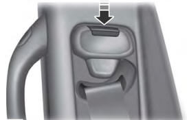
Seatbelt Height Adjustment
WARNING: Position the seatbelt height adjuster so that the seatbelt rests across the middle of your shoulder. Failure to adjust the seatbelt correctly could reduce its effectiveness and increase the risk of injury in a crash.
Copyright © 2025 www.foexplorer.com