Ford Explorer: Automatic Transmission - 10-Speed Automatic Transmission – 10R60 / Description and Operation - F Clutch
Overview
.jpg)
| Item | Description |
| 1 | SSF |
| 2 | F clutch control valve |
| 3 | F clutch latch valve |
| 4 | F clutch apply circuit |
| 5 | F clutch piston |
| 6 | F clutch assembly |
| 7 | Ring gear No. 4 |
| 8 | Planetary carrier No. 1 |
Ring gear No. 4 is mechanically connected to planetary carrier No. 1 and connected to the F clutch. When the F clutch applies, the ring gear No. 4 may be connected to ring gear No. 2 through the C clutch. Ring gear No. 4 may also connect to planetary carrier No. 3 through the D clutch.
F Clutch Exploded View
.jpg)
| Item | Description |
| 1 | Planetary carrier No. 1 |
| 2 | CDF clutch cylinder |
| 3 | F clutch piston |
| 4 | F clutch piston return spring |
| 5 | F clutch balance dam |
| 6 | F clutch apply ring |
| 7 | F clutch friction plates |
| 8 | F clutch steel plates |
| 9 | F clutch pressure plate |
| 10 | Cylinder (clutch and planetary container) |
| 11 | Ring gear No. 4 |
F Clutch Hydraulic Circuits
.jpg)
| Item | Description |
| 1 | Line pressure |
| 2 | Pump output |
| 3 | F clutch control valve |
| 4 | SSF |
| 5 | Control pressure to latch valve |
| 6 | F clutch latch valve |
| 7 | Apply pressure to mechanical F clutch |
| 8 | Mechanical F clutch |
| 9 | Elevated exhaust pressure |
| 10 | Clutch exhaust |
F Clutch Hydraulic Operation
Line pressure is supplied to the F clutch control valve and the F clutch latch valve. As SSF turns on, it moves the control valve allowing regulated line pressure to flow to the F clutch latch valve and then to the mechanical F clutch. When the regulated line pressure in the F clutch control circuit reaches approximately 689 kPa (100 psi), the mechanical F clutch is fully applied. The pressure in the F clutch control circuit moves the F clutch latch valve to the left which allows line pressure to hold the mechanical F clutch applied.
F Clutch Hydraulic Passages
.jpg)
.jpg)
.jpg)
.jpg)
 Description and Operation - E Clutch
Overview
Item
Description
1
SSE
2
E clutch control valve
3
Clutch gain control valve
4
E cl..
 Description and Operation - Low One-Way Clutch Assembly
One-Way Clutch (OWC) Exploded View
Item
Description
1
Front support assembly
2
One-Way Clutch (OWC)
3
Sun gear No...
Other information:
Ford Explorer 2020-2025 Service Manual: Description and Operation - Second Row Seats - Overview
Overview Heated Seats If equipped with the heated seat system, the rear seat cushion and backrest can be heated at one of two levels on demand. The components of the rear heated seat system include: Seat cushion heater mat (LH/ RH) Seat backrest heater mat (LH/ RH) Heated seat module (attached to the underside of the RH second row seat cushion frame) Heated seat switches (..
Ford Explorer 2020-2025 Owners Manual: Navigation
Note: For more information, refer to our website. Select the navigation option on the feature bar. A Map view menu. B Zoom out. C Zoom in. D Route guidance menu. E Destination entry menu. Setting a Destination Destination Entry Menu Setting a Destination Using the Text Entry Screen A Text entry field...
Categories
- Manuals Home
- 6th Generation Explorer Owners Manual
- 6th Generation Explorer Service Manual
- Engine
- General Procedures - Transmission Fluid Drain and Refill
- Removal and Installation - Front Halfshaft Speed Sensor
- New on site
- Most important about car
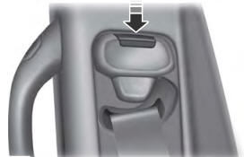
Seatbelt Height Adjustment
WARNING: Position the seatbelt height adjuster so that the seatbelt rests across the middle of your shoulder. Failure to adjust the seatbelt correctly could reduce its effectiveness and increase the risk of injury in a crash.