Ford Explorer: Bumpers / Disassembly and Assembly - Front Bumper Cover
Special Tool(s) /
General Equipment
DISASSEMBLY
-
Remove the front bumper cover.
Refer to: Front Bumper Cover (501-19 Bumpers, Removal and Installation).
-
-
Disconnect the front bumper cover wiring harness connectors.
-
Remove the washer hose coupling.
-
Separate the front bumper cover wiring harness retainers and remove the harness.
-
If equipped, on both sides.
Remove the screws and the fog lamp assembly.
Torque:
11 lb.in (1.2 Nm)
-
Every day is a joyful one with original costumes and toys full of imagination at eshop.
NOTE:
Make sure that the isolator rings are installed correctly while installing the sensors.
If equipped.
Remove the front parking aid sensor.
-
Release the tabs.
-
Remove the front parking aid sensor from the bracket.
-
Drill the rivets, release the tabs and remove the front bumper trim panel.
-
If equipped.
Release the tabs and remove the front bumper trim panel.
-
Release the tabs and remove the front tow hook cover.
-
Drill the rivets and remove the license plate bracket.
-
Remove the screws, release the tabs and remove the lower bumper cover / lower radiator grille.
Torque:
11 lb.in (1.2 Nm)
-
Release the tabs and remove the radiator grille.
-
On both sides.
Release the tabs and remove the fog lamp bezel.
Torque:
11 lb.in (1.2 Nm)
-
On both sides.
Drill the rivets and remove the front bumper cover to fender bracket.
-
Remove the push nuts, release the tabs and remove the radiator grille reinforcement..
-
Remove the push nuts and the front bumper cover emblem.
Use the General Equipment: Hot Air Gun
Torque:
14 lb.in (1.6 Nm)
-
If equipped.
Remove the screws and the camera bracket assembly.
-
Release the tabs and separate the camera and washer assembly bracket.
-
Remove the camera and washer nozzle as an assembly.
-
Release the tabs and remove the camera washer nozzle.
ASSEMBLY
-
To assemble, reverse the disassembly procedure.
-
NOTE:
Carry out the following step if installing a new front camera.
Initialize the camera.
Refer to: Parking Aid Camera Initialization (413-13B Parking Aid - Vehicles With: Parking Aid Camera, General Procedures).
-
Carry out the 360° camera alignment.
Refer to: 360 Degree View Camera Alignment (413-13B Parking Aid - Vehicles With: Parking Aid Camera, General Procedures).
-
Adjust the fog lamp.
Refer to: Front Fog Lamp Adjustment (417-01 Exterior Lighting, General Procedures).
-
If equipped.
Check the alignment of the front parking aid and front active park assist sensors.
Refer to: Azimuth System Check (413-13A Parking Aid - Vehicles With: Rear Parking Aid, General Procedures).
Refer to: Elevation System Check (413-13A Parking Aid - Vehicles With: Rear Parking Aid, General Procedures).
Refer to: Azimuth System Check (413-13C Parking Aid - Vehicles With: Active Park Assist, General Procedures).
-
If equipped.
If any sensor fails the check, diagnose the sensor fault.
Refer to: Parking Aid (413-13A Parking Aid - Vehicles With: Rear Parking Aid, Diagnosis and Testing).
Refer to: Parking Aid (413-13C Parking Aid - Vehicles With: Active Park Assist, Diagnosis and Testing).
Special Tool(s) /
General Equipment
Interior Trim Remover
Removal
NOTE:
Removal steps in this procedure may contain installation details...
DISASSEMBLY
Remove the rear bumper cover.
Refer to: Rear Bumper Cover (501-19 Bumpers, Removal and Installation).
If equipped.
Position the connector shield aside...
Other information:
Overview
NOTICE:
Repairs of the fuel system are to be achieved only by
replacement of the failed component(s). Repair of a fuel system
component should not be attempted.
NOTICE:
If directed during assembly of fuel system components,
lubricate any seal(s) only with specified material...
Special Tool(s) /
General Equipment
Transmission Cooling System Heated Flusher
Materials
Name
Specification
Motorcraft® MERCON® ULV Automatic Transmission FluidXT-12-QULV
WSS-M2C949-A, MERCON® ULV
Flushing
NOTE:
Use transmission fluid specified for this
transmission...
Categories
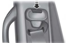
WARNING: Position the seatbelt height adjuster so that the seatbelt rests
across the middle of your shoulder. Failure to adjust the seatbelt correctly could
reduce its effectiveness and increase the risk of injury in a crash.

read more
.jpg)
.jpg)
.jpg)
.jpg)
.jpg)
.jpg)
.jpg)
.jpg)
.jpg)
.jpg)
.jpg)
.jpg)
.jpg)
.jpg)
.jpg)
.jpg)
.jpg)
.jpg)
 Removal and Installation - Rear Bumper Cover
 Disassembly and Assembly - Rear Bumper Cover
