Ford Explorer: Police Equipment / General Procedures - Individual Flash Pattern Programming
Programming
All vehicles
-
IPTV Free Trial.jpg) WARNING:
Police Package warning lights are a
high-intensity Light-Emitting Diode (LED) type. Do not stare directly at
these lights, as doing so may cause temporary blindness and/or eye
damage. Failure to follow this instruction may result in personal
injury.
WARNING:
Police Package warning lights are a
high-intensity Light-Emitting Diode (LED) type. Do not stare directly at
these lights, as doing so may cause temporary blindness and/or eye
damage. Failure to follow this instruction may result in personal
injury.
NOTE: When cycling through flash patterns, most flash patterns include an off/on pattern followed by an inverse on/off pattern. Setting the LEDon one side to the on/off and the other to off/on creates the alternating pattern effect which should not be confused with synchronization which applies to the pattern timing between LED groups. For proper synchronization, the correct flash patterns must be selected for the individual flashing Light Emitting Diodes (LEDs). Refer to the Police Utility Modifier Guide for specific flashing LED patterns.
Disconnect the flashing LED to be programmed.
-
Connect ground to pin 4, component side of the flashing LED.
.jpg) |
-
NOTICE: This step will activate the individual flashing LED . The flashing LED must be active to change the flash pattern.
Connect 12 volts to pin 1, component side of the flashing LED.
-
To change the LED flashing pattern:
-
To cycle forward to the next pattern, connect 12 volts to pin 2, component side of the flashing LED for less than 1 second.
-
To cycle back to the previous pattern, connect 12 volts to pin 2, component side of the flashing LED for greater than 1 second.
-
To cycle forward to the next pattern, connect 12 volts to pin 2, component side of the flashing LED for less than 1 second.
All vehicles
-
WARNING:
Police Package warning lights are a
high-intensity Light-Emitting Diode (LED) type. Do not stare directly at
these lights, as doing so may cause temporary blindness and/or eye
damage. Failure to follow this instruction may result in personal
injury.
NOTE: When cycling through flash patterns, most flash patterns include an off/on pattern followed by an inverse on/off pattern. Setting the LEDon one side to the on/off and the other to off/on creates the alternating pattern effect which should not be confused with synchronization which applies to the pattern timing between LED groups. For proper synchronization, the correct flash patterns must be selected for the individual flashing Light Emitting Diodes (LEDs). Refer to the Police Utility Modifier Guide for specific flashing LED patterns.
Disconnect the flashing LED to be programmed.
-
Connect ground to pin 2, component side of the flashing LED.
.jpg) |
-
NOTICE: This step will activate the individual flashing LED . The flashing LED must be active to change the flash pattern.
Connect 12 volts to pin 5, component side of the flashing LED.
-
To change the LED flashing pattern:
-
To cycle forward to the next pattern, connect 12 volts to pin 3, component side of the flashing LED for less than 1 second.
-
To cycle back to the previous pattern, connect 12 volts to pin 3, component side of the flashing LED for greater than 1 second.
-
To cycle forward to the next pattern, connect 12 volts to pin 3, component side of the flashing LED for less than 1 second.
 General Procedures - Group Flash Pattern Programming
Activation
WARNING:
Police Package warning lights are a high-intensity
Light-Emitting Diode (LED) type. Do not stare directly at these lights,
as doing so may cause temporary blindn..
 Removal and Installation - Exterior Mirror Flashing Light Emitting Diode (LED) Lamps
Special Tool(s) /
General Equipment
Flat Headed Screw Driver
Removal
NOTE:
Removal steps in this procedure may contain installation details...
Other information:
Ford Explorer 2020-2025 Owners Manual: Changing the Engine Air Filter - 3.3L
WARNING: To reduce the risk of vehicle damage and personal burn injuries, do not start your engine with the air cleaner removed and do not remove it while the engine is running. Note: Failure to use the correct air filter element may result in severe engine damage...
Ford Explorer 2020-2025 Owners Manual: Clearing All MyKeys
When you clear your MyKeys, you remove all restrictions and return all MyKeys to their original admin key status at once. To clear all MyKeys of all MyKey settings, use the touchscreen. Switch the ignition on using an admin key. Access the main menu in the touchscreen and then scroll through the menus to begin clearing your MyKey programming...
Categories
- Manuals Home
- 6th Generation Explorer Owners Manual
- 6th Generation Explorer Service Manual
- Removal and Installation - Front Halfshaft Speed Sensor
- General Procedures - Brake Service Mode Activation and Deactivation
- Body and Paint
- New on site
- Most important about car
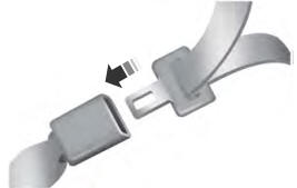
Fastening the Seatbelts
The front outboard and rear safety restraints in the vehicle are combination lap and shoulder belts.