Ford Explorer: Body Closures / General Procedures - Liftgate Alignment
Special Tool(s) /
General Equipment
Materials
| Name |
Specification |
Seam Sealer
TA-2-B, 3M™ 08308, LORD Fusor® 805DTM |
-
|
IPTV Free Trial Adjustment
NOTE:
Removal steps in this procedure may contain installation details.
All alignments
-
Open the liftgate.
-
Position aside the liftgate weatherstrip and the load compartment cover.
-
Remove the liftgate scuff plate trim panel.
-
Release the liftgate scuff plate trim panel clips.
Use the General Equipment: Interior Trim Remover
-
If equipped
Disconnect the keyless entry rear antenna electrical connector.
-
Remove the liftgate striker.
Torque:
18 lb.ft (25 Nm)
Liftgate left and right, up and down alignment
-
Loosen the bolts.
Loosen:
:
2 turn(s)
-
Carefully close the liftgate.
-
Adjust the liftgate as required.
-
Carefully open the liftgate.
-
Tighten the bolts.
Torque:
22 lb.ft (30 Nm)
Liftgate in and out alignment
-
Adjust the stops.
-
On both sides
Remove pin type retainer and the drip moulding.
-
On both sides
Remove the hinge cover.
-
Carefully close the liftgate.
-
On both sides
Loosen the bolts.
Loosen:
:
2 turn(s)
-
Adjust the liftgate as required.
-
On both sides
Tighten the bolts.
Torque:
26 lb.ft (35 Nm)
-
On both sides
Apply seam sealer
Material: Seam Sealer
/ TA-2-B, 3M™ 08308, LORD Fusor® 805DTM
All alignments
-
Inspect the body-to-liftgate door alignment.
-
Install the position aside and removed components.
-
If equipped with power liftgate, carry out the power liftgate initialization.
Refer to: Power Liftgate Initialization (501-03 Body Closures, General Procedures).
Adjustment
NOTE:
Removal steps in this procedure may contain installation details.
All alignments
Remove the hood latch.
Refer to: Hood Latch (501-14 Handles, Locks, Latches and..
Initialization
Disconnect the battery or remove the RGTM fuse(s).
Refer to: Battery Disconnect and Connect (414-01 Battery, Mounting and Cables, General Procedures)...
Other information:
Removal
NOTE:
Removal steps in this procedure may contain installation details.
Push the stop tabs inwards and fully lower the glove compartment.
Remove the glove compartment check strap.
Remove the bolts and the glove compartment assembly...
SECURICODE™ Keyless Entry Keypad
The keypad is near the driver window. It illuminates when touched.
Note: If you enter your entry code too fast on the keypad, the unlock function
may not work. Enter your entry code again more slowly.
You can use the keypad to do the following:
Lock or unlock the doors...
Categories
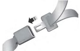
The front outboard and rear safety restraints in the vehicle are combination
lap and shoulder belts.
read more
.jpg)
.jpg)
.jpg)
.jpg)
.jpg)
.jpg)
.jpg)
.jpg)
.jpg)
.jpg)
.jpg)
.jpg)
.jpg)
.jpg)
.jpg)
.jpg)
 General Procedures - Hood Alignment
 General Procedures - Power Liftgate Initialization