Ford Explorer: Driver and Passenger Airbags / Proper Driver and Front Passenger Seating Adjustment
WARNING: National Highway Traffic Safety Administration (NHTSA) recommends a minimum distance of at least 10 in (25 cm) between an occupant's chest and the driver airbag module.
To properly position yourself away from the airbag:
- Move your seat to the rear as far as you can while still reaching the pedals comfortably.
- Recline the seat slightly (one or two degrees) from the upright position.
After all occupants have adjusted their seats and put on seatbelts, it is very important that they continue to sit properly. A properly seated occupant sits upright, leaning against the seatback, and centered on the seat cushion, with their feet comfortably extended on the floor. Sitting improperly can increase the chance of injury in a crash event. For example, if an occupant slouches, lies down, turns sideways, sits forward, leans forward or sideways, or puts one or both feet up, the chance of injury during a crash is greatly increased.
 Driver and Passenger Airbags
WARNING: Do not place your arms on the airbag cover or through the steering
wheel. Failure to follow this instruction could result in personal injury...
 Children and Airbags
WARNING: Airbags can kill or injure a child in a child restraint. Never
place a rear-facing child restraint in front of an active airbag. If you must use
a forward-facing child restraint in the fr..
Other information:
Ford Explorer 2020-2025 Service Manual: Description and Operation - Transmission Description - System Operation and Component Description
System Diagram Item Description 1 SSB 2 SSC 3 SSD 4 SSE 5 SSF 6 LPC 7 TSS 8 ISSB 9 Transmission 10 Transmission 11 TFT 12 TRS 13 SSA 14 PCM 15 TCC 16 OSS 17 ISSA 18 GSM 19 PBW Network Message Chart Broadcast Message Originating Module Message Purpose..
Ford Explorer 2020-2025 Owners Manual: The Better Business Bureau (BBB) Auto Line Program (U.S. Only)
Your satisfaction is important to Ford Motor Company and to your dealer. If a warranty concern has not been resolved using the three-step procedure outlined earlier in this chapter in the Getting the Services you need section, you may be eligible to participate in the BBB AUTO LINE program...
Categories
- Manuals Home
- 6th Generation Explorer Owners Manual
- 6th Generation Explorer Service Manual
- Electric Parking Brake
- Removal and Installation - All-Wheel Drive (AWD) Module
- Removal and Installation - Liftgate Trim Panel
- New on site
- Most important about car
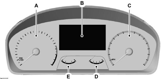
Gauges
4 Inch Display

A - Tachometer.
B - Information display.
C - Speedometer.
D - Fuel gauge.
E - Engine coolant temperature gauge.
