Ford Explorer: Information and Entertainment System - General Information - Vehicles Without: SYNC 3 / Removal and Installation - Audio Unit Antenna Cable
Special Tool(s) /
General Equipment
Removal
Instrument panel AM/FM coaxial cable
-
Remove the floor console.
Refer to: Floor Console (501-12 Instrument Panel and Console, Removal and Installation).
-
Remove the RH front scuff plate trim panel.
Refer to: Front Scuff Plate Trim Panel (501-05 Interior Trim and Ornamentation, Removal and Installation).
-
NOTE:
One screw on each side.
Remove the screws.
Torque:
22 lb.in (2.5 Nm)
-
Release the clips and position the center dash lower trim panel out.
-
Disconnect the electrical connectors and remove the center dash lower trim panel.
-
Disconnect the electrical connector.
-
Disconnect the electrical connector.
Main body harness AM/FM coaxial cable
-
Remove both front seats.
Refer to: Front Seat (501-10A Front Seats, Removal and Installation).
-
Remove the floor console.
Refer to: Floor Console (501-12 Instrument Panel and Console, Removal and Installation).
-
Remove the RH front scuff plate trim panel.
Refer to: Front Scuff Plate Trim Panel (501-05 Interior Trim and Ornamentation, Removal and Installation).
-
Remove the lower B-pillar trim panels.
Refer to: B-Pillar Trim Panel (501-05 Interior Trim and Ornamentation, Removal and Installation).
-
Remove the LH lower C-pillar trim panel.
Refer to: C-Pillar Trim Panel (501-05 Interior Trim and Ornamentation, Removal and Installation).
-
Remove the LH loadspace trim panel.
Refer to: Loadspace Trim Panel - Police (501-05 Interior Trim and Ornamentation, Removal and Installation).
-
Lower the headliner.
Refer to: Headliner - Lowering (501-05 Interior Trim and Ornamentation, Removal and Installation).
-
Disconnect the electrical connector.
-
Disconnect the electrical connector.
-
Position the rear carpet for harness access.
Liftgate AM/FM Coaxial cable
-
Lower the headliner.
Refer to: Headliner - Lowering (501-05 Interior Trim and Ornamentation, Removal and Installation).
-
Release the clips and remove the liftgate center upper trim panel.
Use the General Equipment: Interior Trim Remover
-
Disconnect the electrical connector.
-
Disconnect the AM/FM antenna amplifier connector.
Installation
Instrument panel AM/FM coaxial cable
NOTE:
The original equipment AM/FM antenna coaxial cable is
part of the wiring harness and cannot be removed. This procedure refers
to replacement of the cable only by overlaying the cable.
-
Cut the electrical connector end from the existing cable.
-
Cut the electrical connector end from the existing cable.
-
Install the new coaxial cable.
-
Route the new audio unit antenna cable following the routing shown.
-
Secure the new audio unit antenna cable, as necessary, to prevent NVH concerns.
-
To install, reverse the removal procedure.
Main body harness AM/FM coaxial cable
NOTE:
The original equipment AM/FM antenna coaxial cable is
part of the wiring harness and cannot be removed. This procedure refers
to replacement of the cable only by overlaying the cable.
-
Cut the electrical connector end from the existing cable.
-
NOTICE:
Use care to prevent damage to the wiring harness.
Cut the end off the rear roof coaxial cable.
-
Release the retaining tabs.
-
Remove the coaxial cable end from the connector shell.
-
Install the new coaxial cable.
-
Route the new audio unit antenna cable following the routing shown.
-
Secure the new audio unit antenna cable, as necessary, to prevent NVH concerns.
-
Install the cable end into the harness connector.
-
To install, reverse the removal procedure.
Liftgate AM/FM Coaxial cable
NOTE:
The original equipment AM/FM antenna coaxial cable is
part of the wiring harness and cannot be removed. This procedure refers
to replacement of the cable only by overlaying the cable.
-
Cut the end off the AM/FM amplifier cable.
-
Disconnect the electrical connector.
-
NOTICE:
Use care to prevent damage to the wiring harness.
Cut the end off the AM/FM liftgate coaxial cable.
-
Release the retaining tabs.
-
Remove the coaxial cable end from the connector shell.
-
Install the new coaxial cable.
-
Route the new audio unit antenna cable following the routing shown.
-
Secure the new audio unit antenna cable, as necessary, to prevent NVH concerns.
-
Install the cable end into the harness connector.
-
To install, reverse the removal procedure.
Removal
NOTE:
Removal steps in this procedure may contain installation details.
All vehicles
NOTE:
If installing a new module, it is necessary to
upload the module configuration inform..
Special Tool(s) /
General Equipment
Interior Trim Remover
Removal
NOTE:
Removal steps in this procedure may contain installation details...
Other information:
Removal
WARNING:
The following procedure prescribes critical repair steps
required for correct restraint system operation during a crash. Follow
all notes and steps carefully. Failure to follow step instructions may
result in incorrect operation of the restraint system and increases the
risk of serious personal injury or death in a crash...
Removal
NOTE:
Removal steps in this procedure may contain installation details.
NOTE:
Lighting and siren control module switch pad shown, lighting relay center switch pad similar.
NOTE:
The switch pad is mounted by the individual police department and the mounting location will vary...
Categories
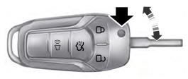
Use the key blade to start your vehicle and unlock or lock the driver door from
outside your vehicle. The integrated keyhead transmitter functions as a programmed
ignition key that operates all the locks and starts your vehicle, as well as a remote
control.
read more
.jpg)
.jpg)
.jpg)
.jpg)
.jpg)
.jpg)
.jpg)
.jpg)
.jpg)
.jpg)
.jpg)
.jpg)
.jpg)
.jpg)
.jpg)
.jpg)
.jpg)
.jpg)
.jpg)
 Removal and Installation - Audio Front Control Module (ACM)
 Removal and Installation - Front Control/Display Interface Module (FCDIM)