Ford Explorer: Electrical
Ford Explorer 2020-2026 Service Manual / Electrical
- Climate Control System
- Instrumentation and Warning Systems
- Instrument Panel and Interior Switches Illumination
- Instrumentation, Message Center and Warning Chimes
- Instrumentation and Warning Systems
- Instrumentation, Message Center and Warning Chimes
- Horn
- Parking Aid - Vehicles With: Rear Parking Aid
- Pedestrian Alert System
- Battery and Charging System
- Charging System - General Information
- Battery, Mounting and Cables
- Generator and Regulator
- High Voltage Battery, Mounting and Cables
- Battery and Charging System
- Information and Entertainment Systems
- Information and Entertainment System - General Information - Vehicles Without: SYNC 3
- Information and Entertainment System - General Information - Vehicles With: SYNC 3
- Lighting
- Electrical Distribution
- Electronic Feature Group
- Perimeter Anti-Theft Alarm
- Passive Anti-Theft System (PATS)
- Cruise Control
- Cruise Control - Vehicles With: Adaptive Cruise Control With Lane Centering
- Electronic Feature Group
 Removal and Installation - Accelerator Pedal
Removal
NOTICE:
Activate the parking brake.
NOTE:
Make sure the vehicle powertrain is powered off.
NOTE:
Removal steps in this procedure may contain installation details...

Other information:
Ford Explorer 2020-2026 Service Manual: Removal and Installation - Rear Side Marker Flashing Light Emitting Diode (LED) Lamps
Special Tool(s) / General Equipment Interior Trim Remover Removal NOTE: Removal steps in this procedure may contain installation details. NOTE: LH lamp assembly shown, RH lamp assembly is similar. Remove the loadspace trim panel...
Ford Explorer 2020-2026 Service Manual: Removal and Installation - Timing Chain
Removal NOTICE: Do not loosen or remove the crankshaft pulley bolt without first installing the special tools as instructed in this procedure. The crankshaft pulley and the crankshaft timing sprocket are not keyed to the crankshaft. The crankshaft, the crankshaft sprocket and the pulley are fitted together by friction...
Categories
- Manuals Home
- 6th Generation Explorer Owners Manual
- 6th Generation Explorer Service Manual
- Fuel Filler Funnel Location & Running Out of Fuel
- Engine - 2.3L EcoBoost (201kW/273PS)
- Interior Trim and Ornamentation
- New on site
- Most important about car
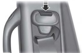
Seatbelt Height Adjustment
WARNING: Position the seatbelt height adjuster so that the seatbelt rests across the middle of your shoulder. Failure to adjust the seatbelt correctly could reduce its effectiveness and increase the risk of injury in a crash.
Copyright © 2026 www.foexplorer.com