Ford Explorer: Electronic Engine Controls - 2.3L EcoBoost (201kW/273PS) / Removal and Installation - Camshaft Position (CMP) Sensor
Materials
| Name | Specification |
|---|---|
| Motorcraft® Silicone Brake Caliper Grease and Dielectric Compound XG-3-A |
ESE-M1C171-A |
Removal
NOTE: Removal steps in this procedure may contain installation details.
Exhaust Camshaft Position (CMP) Sensor
-
NOTICE: Do not pull the engine appearance cover forward or sideways to remove. Failure to press straight upward on the underside of the cover at the attachment points may result in damage to the cover or engine components.
-
Remove the engine appearance cover nuts.
-
Place your hand under the engine appearance
cover at each grommet location and pull straight up to release each
grommet from the studs.
-
After all of the grommets have been released
from the studs, remove the appearance cover from the engine.
-
Remove the engine appearance cover nuts.
.jpg) |
-
-
Disconnect the electrical connector. Remove the bolt and the exhaust CMP sensor.
Torque: 97 lb.in (11 Nm)
-
Disconnect the electrical connector. Remove the bolt and the exhaust CMP sensor.
.jpg) |
Intake Camshaft Position (CMP) Sensor
-
NOTICE: Do not pull the engine appearance cover forward or sideways to remove. Failure to press straight upward on the underside of the cover at the attachment points may result in damage to the cover or engine components.
-
Remove the engine appearance cover nut.
-
Place your hand under the engine appearance
cover at each grommet location and pull straight up to release each
grommet from the studs.
-
After all of the grommets have been released
from the studs, remove the appearance cover from the engine.
-
Remove the engine appearance cover nut.
|
-
Disconnect the electrical connector. Remove the bolt and the intake CMP sensor.
Torque: 97 lb.in (11 Nm)
.jpg) |
Installation
-
NOTE: Before installation, lubricate the CMP sensor O-ring seal with clean engine oil.
To install, reverse the removal procedure.
-
-
NOTE: Lubricating the grommets with silicone grease will aid in the installation of the engine appearance cover, and any future removal and installation of the cover.
Lubricate each grommet with silicone grease.
Material: Motorcraft® Silicone Brake Caliper Grease and Dielectric Compound / XG-3-A (ESE-M1C171-A)
-
Position the engine appearance cover onto engine with the grommets aligned with the studs.
-
Press down on the engine appearance cover at each grommet location to attach the grommets onto the studs.
-
Install the engine appearance cover nut.
Torque: 44 lb.in (5 Nm)
-
If the engine appearance cover stud bolt is loosened
or removed, it must be installed/tightened into the valve cover.
Torque: 62 lb.in (7 Nm)
-
|
 Diagnosis and Testing - Electronic Engine Controls
Diagnostic Trouble Code (DTC) Chart
Diagnostics in this manual assume a certain skill level and knowledge of Ford-specific diagnostic practices. REFER to: Diagnostic Methods (100-00 General Informati..
 Removal and Installation - Catalyst Monitor Sensor
Special Tool(s) /
General Equipment
303-476
(T94P-9472-A)
Socket, Exhaust Gas Oxygen SensorTKIT-1994-LM/MTKIT-1994-FTKIT-1994-FLM/FM
Materials
Name
Specification
Motorcraft® Hig..
Other information:
Ford Explorer 2020-2025 Service Manual: Removal and Installation - A-Pillar Outer Panel Section and Reinforcement
Special Tool(s) / General Equipment Resistance Spotwelding Equipment Hot Air Gun 8 mm Drill Bit MIG/MAG Welding Equipment Spot Weld Drill Bit Locking Pliers Materials Name Specification Seam SealerTA-2-B, 3M™ 08308, LORD Fusor® 805DTM - Flexible Foam Repair3M™ 08463, LORD Fusor® 121 - Removal WARNING: Electri..
Ford Explorer 2020-2025 Service Manual: Removal and Installation - Downstream Catalytic Converter
Removal NOTE: Removal steps in this procedure may contain installation details. Refer to: Health and Safety Precautions (100-00 General Information, Description and Operation). With the vehicle in NEUTRAL, position it on a hoist...
Categories
- Manuals Home
- 6th Generation Explorer Owners Manual
- 6th Generation Explorer Service Manual
- Interior Trim and Ornamentation
- Auxiliary Power Points
- General Procedures - Transmission Fluid Drain and Refill
- New on site
- Most important about car
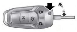
Integrated Keyhead Transmitter (If Equipped)
Use the key blade to start your vehicle and unlock or lock the driver door from outside your vehicle. The integrated keyhead transmitter functions as a programmed ignition key that operates all the locks and starts your vehicle, as well as a remote control.