Ford Explorer: Driveshaft / Removal and Installation - Driveshaft Flexible Coupling
Removal
NOTE: The maximum articulation of the flex coupling is 4 degrees. The maximum articulation of any U-joint is 25 degrees. The maximum articulation of the center CV-joint is 20 degrees. The maximum articulation of the rear axle CV-joint is 15 degrees. If the flex coupling or any CV-Joint or U-joint of the driveshaft is articulated further than the maximum allowable degrees damage may occur.
-
Remove the exhaust flexible pipe.
Refer to: Exhaust Flexible Pipe (309-00C Exhaust System - 3.3L Duratec-V6, Removal and Installation).
Refer to: Exhaust Flexible Pipe (309-00D Exhaust System - 3.3L Duratec-V6 – Hybrid (BP), Removal and Installation).
-
If equipped.
Remove the bolts and the transfer case heat shield.
.jpg) |
-
-
Remove and discard the driveshaft flex coupling to transfer case or transmission flange bolts.
-
Separate the flex coupling from the transfer case or transmission flange.
-
Position aside and support the driveshaft.
-
Remove and discard the driveshaft flex coupling to transfer case or transmission flange bolts.
.jpg) |
-
Remove and discard the bolts and remove the flex coupling.
.jpg) |
Installation
-
Inspect the driveshaft alignment bushing for damage or excessive wear. Replace if necessary.
Refer to: Driveshaft Alignment Bushing (205-01 Driveshaft, Disassembly and Assembly).
.jpg) |
-
NOTE: Make sure that the threaded holes are clean and free of foreign matter.
NOTE: Make sure that the mating faces are clean and free of foreign material.
Clean and inspect the mating surfaces of driveshaft flexible coupling. Clean-off any contamination or excess grease off of transfer case or transmission flange and pilot spigot.
.jpg) |
-
NOTE: Cracks forming in the flex coupling are normal.
Inspect the flex coupling for damage. If internal windings (threads) are visible, replace the flex coupling.
.jpg) |
-
NOTICE: The protruding flex coupling bushings must align with the driveshaft flange bolts as shown in the picture.
NOTE: Do not force the flex coupling bushing on the driveshaft or damage will occur.
NOTE: Make sure that the arrows moulded on flex coupling point towards the bolt holes on the flange.
Position the driveshaft flex coupling to the driveshaft flange and install the new bolts.
Torque: 81 lb.ft (110 Nm)
.jpg) |
-
NOTICE: Do not over articulate the driveshaft or damage may occur.
NOTICE: The protruding flex coupling bushings must align with the transfer case output flange bolts as shown in the picture.
NOTE: Do not force the flex coupling bushing on the transfer case output shaft or damage will occur.
NOTE: Make sure that the arrows moulded on flex coupling point towards the bolt holes on the flange.
-
Position the driveshaft flex coupling to the transfer case or transmission flange.
-
Install the new driveshaft flex coupling to transfer case or transmission flange bolts.
Torque: 81 lb.ft (110 Nm)
-
Position the driveshaft flex coupling to the transfer case or transmission flange.
.jpg) |
-
NOTICE: Ensure that the transfer case heatshield does not contact the driveshaft flex coupling.
If equipped.
Install the bolts and the transfer case heat shield.
Torque: 21 lb.ft (28 Nm)
.jpg) |
-
Install the exhaust flexible pipe.
Refer to: Exhaust Flexible Pipe (309-00C Exhaust System - 3.3L Duratec-V6, Removal and Installation).
Refer to: Exhaust Flexible Pipe (309-00D Exhaust System - 3.3L Duratec-V6 – Hybrid (BP), Removal and Installation).
 General Procedures - Driveshaft Runout and Balancing
Special Tool(s) /
General Equipment
100-002
(TOOL-4201-C)
Holding Fixture with Dial Indicator Gauge
Inspection
NOTE:
Driveline vibration exhibits a higher frequency and lower
amplit..
 Removal and Installation - Front Driveshaft
Materials
Name
Specification
Slip Yoke Grease5L3Z-19A506-A
-
Removal
All vehicles
Remove the transfer case.
3...
Other information:
Ford Explorer 2020-2025 Service Manual: Removal and Installation - Blower Motor Control Module
Removal Remove the push pins and the passenger side insulation panel. Disconnect the electrical connector. Remove the screws and the blower motor control module. Disconnect the electical connector...
Ford Explorer 2020-2025 Service Manual: General Procedures - Valve Guide Inner Diameter
Check NOTE: Refer to the appropriate Section 303-01 for the specification. NOTE: Valve guides tend to wear in an hourglass pattern. The ball gauge can be inserted into the combustion chamber side of the valve guide, if necessary. Use a ball gauge to determine the inside diameter of the valve guides in 2 directions at the top, middle and bottom of the valve guide...
Categories
- Manuals Home
- 6th Generation Explorer Owners Manual
- 6th Generation Explorer Service Manual
- Interior Trim and Ornamentation
- Diagnosis and Testing - Parking Brake - Vehicles With: Electric Brake Booster
- Removal and Installation - All-Wheel Drive (AWD) Module
- New on site
- Most important about car
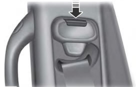
Seatbelt Height Adjustment
WARNING: Position the seatbelt height adjuster so that the seatbelt rests across the middle of your shoulder. Failure to adjust the seatbelt correctly could reduce its effectiveness and increase the risk of injury in a crash.

