Ford Explorer: Engine Emission Control - 2.3L EcoBoost (201kW/273PS) / Removal and Installation - Exhaust Gas Recirculation (EGR) Cooler
Removal
NOTE:
Removal steps in this procedure may contain installation details.
-
Drain the cooling system.
Refer to: Engine Cooling System Draining, Vacuum Filling and Bleeding (303-03A Engine Cooling - 2.3L EcoBoost (201kW/273PS), General Procedures).
-
Remove the EGR valve.
Refer to: Exhaust Gas Recirculation (EGR) Valve (303-08A Engine Emission Control - 2.3L EcoBoost (201kW/273PS), Removal and Installation).
-
Remove the EGR back pressure sensor.
Refer to: Exhaust Gas Recirculation (EGR) Back Pressure Sensor (303-08A Engine Emission Control - 2.3L EcoBoost (201kW/273PS), Removal and Installation).
-
-
Remove the fastener.
Torque:
97 lb.in (11 Nm)
-
Remove the fastener and mounting bracket.
Torque:
97 lb.in (11 Nm)
-
Remove the bolt and the coolant tube.
Torque:
97 lb.in (11 Nm)
-
Loosen the clamp and detach the retainer.
-
-
Remove the fasteners.
Torque:
97 lb.in (11 Nm)
-
Remove and discard the gasket.
-
Disconnect the electrical connector and detach the retainer clips.
-
-
Remove the fastener.
Torque:
97 lb.in (11 Nm)
-
Remove the fastener and EGR mounting bracket.
Torque:
97 lb.in (11 Nm)
-
Remove the fastener and position aside the coolant hose.
Torque:
97 lb.in (11 Nm)
-
-
Remove the bolt.
Torque:
97 lb.in (11 Nm)
-
Remove and discard the gasket.
Installation
-
-
Tighten the bolts.
Torque:
97 lb.in (11 Nm)
-
-
Tighten the bolts.
Torque:
97 lb.in (11 Nm)
-
To install, reverse the removal procedure.
Removal
NOTE:
Removal steps in this procedure may contain installation details.
Disconnect the EGR coolant outlet temperature sensor electrical connector...
Removal
NOTE:
Removal steps in this procedure may contain installation details.
Remove the EGR inlet tube.
Refer to: Exhaust Gas Recirculation (EGR) Inlet Tube (303-08A Engine Emission..
Other information:
Materials
Name
Specification
Motorcraft® Silicone Brake Caliper Grease and Dielectric CompoundXG-3-A
ESE-M1C171-A
Removal
NOTE:
Removal steps in this procedure may contain installation details.
Release the fuel system pressure...
Special Tool(s) /
General Equipment
Hose Clamp(s)
Removal
NOTE:
Removal steps in this procedure may contain installation details.
Disconnect the electrical connector.
Remove the locking clip and remove the cabin heater coolant temperature sensor...
Categories
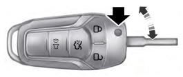
Use the key blade to start your vehicle and unlock or lock the driver door from
outside your vehicle. The integrated keyhead transmitter functions as a programmed
ignition key that operates all the locks and starts your vehicle, as well as a remote
control.
read more
.jpg)
.jpg)
.jpg)
.jpg)
.jpg)
.jpg)
.jpg)
.jpg)
.jpg)
.jpg)
 Removal and Installation - Exhaust Gas Recirculation (EGR) Coolant Outlet Temperature Sensor
 Removal and Installation - Exhaust Gas Recirculation (EGR) Outlet Tube