Ford Explorer: Exterior Trim and Ornamentation / Removal and Installation - Front Door Upper Moulding
Ford Explorer 2020-2025 Service Manual / Body and Paint / Body and Paint / Exterior Trim and Ornamentation / Removal and Installation - Front Door Upper Moulding
Removal
NOTE: Removal steps in this procedure may contain installation details.
NOTE: LH side shown, RH similar.
All vehicles
-
Lower the door window glass completely.
.jpg) |
-
Remove the exterior mirror.
Refer to: Exterior Mirror (501-09 Rear View Mirrors, Removal and Installation).
-
Remove the upper belt moulding screw at rear of the door.
Torque: 12 lb.in (1.3 Nm)
.jpg) |
-
Using a non-marring trim tool, disengage the moulding from the channel in the door and remove the moulding.
.jpg) |
-
Position the glass run weatherstrip aside.
.jpg) |
-
Remove the screw on the upper door frame.
Torque: 12 lb.in (1.3 Nm)
.jpg) |
Vehicles With: Keyless Vehicle System
-
Remove the LHF door trim panel.
Refer to: Front Door Trim Panel (501-05 Interior Trim and Ornamentation, Removal and Installation).
-
Disconnect the electrical connector.
.jpg) |
-
Detach the wiring harness connector.
.jpg) |
-
NOTE: The keypad actuator can be serviced separately from the moulding if required.
Remove the screws and detach the retainer clip.
Torque: 8 lb.in (0.9 Nm)
.jpg) |
All vehicles
-
NOTE: Standard front door upper moulding shown, keyless entry similar.
-
Remove the retainer clips and dislodge the 4way clip.
-
Remove the front door upper moulding.
-
Remove the retainer clips and dislodge the 4way clip.
.jpg) |
Installation
Vehicles With: Keyless Vehicle System
-
Install the wiring harness connector.
|
-
Connect the electrical connector.
|
-
Install the LHF door trim panel.
Refer to: Front Door Trim Panel (501-05 Interior Trim and Ornamentation, Removal and Installation).
All vehicles
-
Install the screw on the upper door frame.
Torque: 12 lb.in (1.3 Nm)
|
-
Reposition the glass run weatherstrip.
.jpg) |
-
Install the upper belt moulding.
.jpg) |
-
Install the upper belt moulding screw at rear of the door.
Torque: 12 lb.in (1.3 Nm)
|
-
Install the exterior mirror.
Refer to: Exterior Mirror (501-09 Rear View Mirrors, Removal and Installation).
 Removal and Installation - Front Door Moulding
Special Tool(s) /
General Equipment
Interior Trim Remover
Removal
NOTE:
Removal steps in this procedure may contain installation details...
 Removal and Installation - Front Fender Moulding
Removal
NOTE:
Removal steps in this procedure may contain installation details.
NOTE:
LH side shown, RH side similar.
Remove the screws...
Other information:
Ford Explorer 2020-2025 Service Manual: Removal and Installation - Headlamp Control Module (HCM)
Removal NOTE: This step is only necessary if the HCM is being replaced. NOTE: If installing a new module, it is necessary to upload the module configuration information to the scan tool prior to removing the module. This information must be downloaded into the new module after installation...
Ford Explorer 2020-2025 Owners Manual: Proper Driver and Front Passenger Seating Adjustment
WARNING: National Highway Traffic Safety Administration (NHTSA) recommends a minimum distance of at least 10 in (25 cm) between an occupant's chest and the driver airbag module. To properly position yourself away from the airbag: Move your seat to the rear as far as you can while still reaching the pedals comfortably...
Categories
- Manuals Home
- 6th Generation Explorer Owners Manual
- 6th Generation Explorer Service Manual
- Removal and Installation - Front Halfshaft Speed Sensor
- Traction Control
- Removal and Installation - Liftgate Trim Panel
- New on site
- Most important about car
Gauges
4 Inch Display
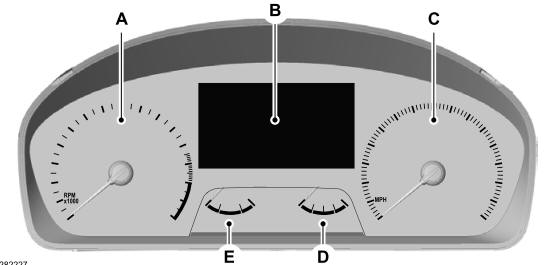
A - Tachometer.
B - Information display.
C - Speedometer.
D - Fuel gauge.
E - Engine coolant temperature gauge.
Copyright © 2025 www.foexplorer.com