Ford Explorer: Engine - 2.3L EcoBoost (201kW/273PS) / Removal and Installation - Oil Cooler
Ford Explorer 2020-2025 Service Manual / Powertrain / Engine / Engine - 2.3L EcoBoost (201kW/273PS) / Removal and Installation - Oil Cooler
Special Tool(s) / General Equipment
| Hose Clamp Remover/Installer | |
| Locking Pliers |
Removal
NOTE: During engine repair procedures, cleanliness is extremely important. Any foreign material (including any material created while cleaning gasket surfaces) that enters the oil passages, coolant passages or the oil pan can cause engine failure.
-
With the vehicle in NEUTRAL, position it on a hoist.
Refer to: Jacking and Lifting - Overview (100-02 Jacking and Lifting, Description and Operation).
-
Remove the bolts and the pin-type retainers and the rear underbody shield.
.jpg) |
-
-
Using hose locking pliers, clamp the oil cooler coolant hoses.
Use the General Equipment: Locking Pliers
-
Using the hose clamp remover, remove the coolant hoses.
Use the General Equipment: Hose Clamp Remover/Installer
-
Using hose locking pliers, clamp the oil cooler coolant hoses.
.jpg) |
-
-
Remove the bolt and the oil cooler.
-
https://magicaliptv.com/iptv-free-trials/
NOTICE: If metal or aluminum material is present in the oil cooler, mechanical concerns exist. Failure to correct these concerns may cause engine failure.
To diagnose mechanical concerns.
Refer to: Engine (303-00 Engine System - General Information, Diagnosis and Testing).
-
Remove the bolt and the oil cooler.
.jpg) |
-
Inspect and replace the oil cooler gasket, if damaged.
.jpg) |
Installation
-
Install the oil cooler and the bolt.
Torque:
Stage 1: 17 lb.ft (22.5 Nm)
Stage 2: 75°
Stage 3: Wait 2s
Stage 4: 15°
|
-
-
Using the hose clamp installer, install the coolant hoses.
Use the General Equipment: Hose Clamp Remover/Installer
-
Remove the hose locking pliers.
-
Using the hose clamp installer, install the coolant hoses.
.jpg) |
-
Install the rear underbody shield, bolts and the pin-type retainers.
Torque: 22 lb.in (2.5 Nm)
|
-
Inspect and adjust the engine coolant level.
Refer to: Specifications (303-03A Engine Cooling - 2.3L EcoBoost (201kW/273PS), Specifications).
 Removal and Installation - Intake Manifold
Materials
Name
Specification
Motorcraft® Silicone Brake Caliper Grease and Dielectric CompoundXG-3-A
ESE-M1C171-A
Removal
NOTICE:
The turbocharger compressor vanes can ..
 Removal and Installation - Oil Pan
Special Tool(s) /
General Equipment
205-153
(T80T-4000-W)
Handle
303-096
(T74P-6150-A)
Installer, Camshaft Front Oil SealTKIT-2009TC-F
303-103
(T74P-6375-A)
Holding Tool, Fl..
Other information:
Ford Explorer 2020-2025 Owners Manual: Four-Wheel Drive
Principle of Operation This system is a proactive system. It has the ability to anticipate wheel slip and transfer torque to the rear wheels before slip occurs. Even when wheel slip is not present, the system is continuously making adjustments to the torque distribution, in an attempt to improve straight line and cornering behavior, both on and off road...
Ford Explorer 2020-2025 Service Manual: Diagnosis and Testing - Flasher Lighting, Siren and Speaker System
Diagnostic Trouble Code (DTC) Chart Diagnostics in this manual assume a certain skill level and knowledge of Ford-specific diagnostic practices. REFER to: Diagnostic Methods (100-00 General Information, Description and Operation). Diagnostic Trouble Code Chart Module DTC Description Action BCM B12F4:1..
Categories
- Manuals Home
- 6th Generation Explorer Owners Manual
- 6th Generation Explorer Service Manual
- General Procedures - Transmission Fluid Drain and Refill
- Engine
- Removal and Installation - Front Halfshaft Speed Sensor
- New on site
- Most important about car
Gauges
4 Inch Display
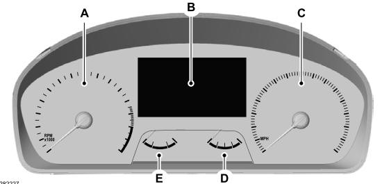
A - Tachometer.
B - Information display.
C - Speedometer.
D - Fuel gauge.
E - Engine coolant temperature gauge.
Copyright © 2025 www.foexplorer.com