Ford Explorer: Rear Suspension / Removal and Installation - Rear Shock Absorber
Special Tool(s) / General Equipment
| Vehicle/Axle Stands |
Removal
NOTICE: Suspension fasteners are critical parts that affect the performance of vital components and systems. Failure of these fasteners may result in major service expense. Use the same or equivalent parts if replacement is necessary. Do not use a replacement part of lesser quality or substitute design. Tighten fasteners as specified.
-
Remove the wheel and tire.
Refer to: Wheel and Tire (204-04A Wheels and Tires, Removal and Installation).
-
NOTICE: Do not attempt to jacking on the front control arm or rear control arm on any vehicle. Damage to control arms may occur.
NOTICE: Make sure that the insulator pads are correctly positioned to prevent direct contact with other components.
Support the rear suspension using an axle stand.
Use the General Equipment: Vehicle/Axle Stands
.jpg) |
-
-
Hold the flag portion of the taper pin.
-
Remove and discard the rear shock absorber lower nut.
-
Hold the flag portion of the taper pin.
.jpg) |
-
Remove and discard the rear shock absorber upper bolts.
.jpg) |
-
NOTE: This step is only necessary when installing a new component.
Remove the rear shock absorber rod nut cap.
.jpg) |
-
NOTICE: Do not use power tools to remove the nut.
NOTE: This step is only necessary when installing a new component.
NOTE: Use the hex-holding feature to prevent the shock absorber rod from turning while removing or installing the shock absorber rod nut.
Remove and discard the rear shock absorber rod nut and Remove the shock absorber top mount.
.jpg) |
-
NOTE: This step is only necessary when installing a new component.
-
Remove the dust shield.
-
Remove the jounce bumper.
-
Remove the dust shield.
.jpg) |
Installation
-
NOTE: This step is only necessary when installing a new component.
-
Install the jounce bumper.
-
Install the dust shield.
-
Install the jounce bumper.
.jpg) |
-
NOTE: This step is only necessary when installing a new component.
NOTE: Use the hex-holding feature to prevent the shock absorber rod from turning while removing or installing the shock absorber rod nut.
Install the new rear shock absorber rod nut.
Torque: 22 lb.ft (30 Nm)
.jpg) |
-
NOTE: This step is only necessary when installing a new component.
Install the rear shock absorber rod nut cap.
.jpg) |
-
-
Install the rear shock absorber and hold the flag portion of the taper pin.
-
Install the new rear shock absorber lower nut.
Torque: 59 lb.ft (80 Nm)
-
Install the rear shock absorber and hold the flag portion of the taper pin.
.jpg) |
-
-
Compress the rear shock absorber and align the rear
shock absorber upper mount under the body alignment pins.
-
Install the new rear shock absorber upper bolts.
Torque: 76 lb.ft (103 Nm)
-
Compress the rear shock absorber and align the rear
shock absorber upper mount under the body alignment pins.
.jpg) |
-
Install the wheel and tire.
Refer to: Wheel and Tire (204-04A Wheels and Tires, Removal and Installation).
-
NOTE: If equipped with dynamic suspension.
Calibrate the suspension height sensor. Connect the scan tool and carry out the Ride Height Calibration routine. Follow the scan tool directions.
 Removal and Installation - Lower Arm Vertical Link
Special Tool(s) /
General Equipment
Vehicle/Axle Stands
Removal
NOTICE:
Suspension fasteners are critical parts that affect the
performance of vital components and systems...
 Removal and Installation - Rear Stabilizer Bar
Removal
NOTICE:
Suspension fasteners are critical parts that affect the
performance of vital components and systems. Failure of these fasteners
may result in major service expense...
Other information:
Ford Explorer 2020-2026 Service Manual: Removal and Installation - Body Control Module (BCM)
Removal NOTE: Removal steps in this procedure may contain installation details. If installing a new BCM, connect a battery charger to the battery to make sure it is charged to maintain proper battery voltage. Refer to: Battery Charging (414-01 Battery, Mounting and Cables, General Procedures)...
Ford Explorer 2020-2026 Service Manual: Removal and Installation - Wireless Accessory Charging Module (WACM)
Removal NOTE: If installing a new module, it is necessary to upload the module configuration information to the scan tool prior to removing the module. This information must be downloaded into the new module after installation. Using a diagnostic scan tool, begin the PMI process for the WACM following the on-screen instructions...
Categories
- Manuals Home
- 6th Generation Explorer Owners Manual
- 6th Generation Explorer Service Manual
- General Procedures - Brake Service Mode Activation and Deactivation
- General Service Information
- Electric Parking Brake
- New on site
- Most important about car
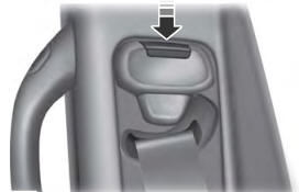
Seatbelt Height Adjustment
WARNING: Position the seatbelt height adjuster so that the seatbelt rests across the middle of your shoulder. Failure to adjust the seatbelt correctly could reduce its effectiveness and increase the risk of injury in a crash.

