Ford Explorer: Rear Suspension / Removal and Installation - Lower Arm Vertical Link
Special Tool(s) / General Equipment
| Vehicle/Axle Stands |
Removal
NOTICE: Suspension fasteners are critical parts that affect the performance of vital components and systems. Failure of these fasteners may result in major service expense. Use the same or equivalent parts if replacement is necessary. Do not use a replacement part of lesser quality or substitute design. Tighten fasteners as specified.
-
Remove the wheel and tire.
Refer to: Wheel and Tire (204-04A Wheels and Tires, Removal and Installation).
-
https://magicaliptv.com/iptv-free-trials/
NOTICE: Do not attempt to jacking on the front control arm or rear control arm on any vehicle. Damage to control arms may occur.
NOTICE: Make sure that the insulator pads are correctly positioned to prevent direct contact with other components.
Use a suitable jack to raise the suspension until the distance between the center of the hub and the lip of the fender is equal to the measurement taken during removal (curb height).
Use the General Equipment: Vehicle/Axle Stands
.jpg) |
-
-
Remove and discard the lower arm vertical link upper bolt and nut.
-
Remove and discard the lower arm vertical link lower bolt and remove the lower arm vertical link.
-
Remove and discard the lower arm vertical link upper bolt and nut.
.jpg) |
Installation
-
NOTICE: Tighten the suspension fasteners with the weight of the vehicle on the wheels and tires or use a suitable jack to raise the suspension to curb height or damage to the bushings may occur.
NOTE: Only tighten the nuts and bolts when the suspension is in the normal drive position.
-
Install the lower arm vertical link and install the new lower arm vertical link upper bolt.
Torque: 76 lb.ft (103 Nm)
-
Install the new lower arm vertical link lower bolt and nut.
Torque: 258 lb.ft (350 Nm)
-
Install the lower arm vertical link and install the new lower arm vertical link upper bolt.
.jpg) |
-
Install the wheel and tire.
Refer to: Wheel and Tire (204-04A Wheels and Tires, Removal and Installation).
 Removal and Installation - Lower Arm
Special Tool(s) /
General Equipment
Vehicle/Axle Stands
Removal
NOTICE:
Suspension fasteners are critical parts that affect the
performance of vital components and systems...
 Removal and Installation - Rear Shock Absorber
Special Tool(s) /
General Equipment
Vehicle/Axle Stands
Removal
NOTICE:
Suspension fasteners are critical parts that affect the
performance of vital components and systems...
Other information:
Ford Explorer 2020-2025 Service Manual: Removal and Installation - Fuel Filler Door Latch
Removal Remove the fuel filler door assembly. Refer to: Fuel Filler Door Assembly (501-03 Body Closures, Removal and Installation). Remove the fuel filler door latch. Release the fuel filler door latch retaining tabs. Remove the fuel filler door latch...
Ford Explorer 2020-2025 Service Manual: Description and Operation - Parking Aid - System Operation and Component Description
System Operation Parking Aid - Audible System Diagram without 360 Degree View Camera Item Description 1 PAM 2 LHR outer sensor 3 LHF outer sensor 4 LHF inner sensor 5 RHF inner sensor 6 RHR outer sensor 7 RHF outer sensor 8 RHR inner sensor 9 LHR inner sensor 10 Parking aid disable switch 1..
Categories
- Manuals Home
- 6th Generation Explorer Owners Manual
- 6th Generation Explorer Service Manual
- Auxiliary Power Points
- Diagnosis and Testing - Parking Brake - Vehicles With: Electric Brake Booster
- General Procedures - Transmission Fluid Drain and Refill
- New on site
- Most important about car
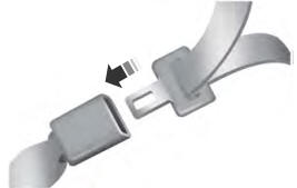
Fastening the Seatbelts
The front outboard and rear safety restraints in the vehicle are combination lap and shoulder belts.