Ford Explorer: Second Row Seats / Removal and Installation - Second Row Seat - Police
Removal
.jpg) WARNING:
The following procedure describes critical repair steps
required for correct seat component installation. Follow all notes and
steps carefully. Do not place any objects between the seat components
and the body of the vehicle, nor any objects within a joint internal to
the seat structure. Failure to follow step instructions may result in
incorrect operation of the seat components and increases the risk of
serious personal injury.
WARNING:
The following procedure describes critical repair steps
required for correct seat component installation. Follow all notes and
steps carefully. Do not place any objects between the seat components
and the body of the vehicle, nor any objects within a joint internal to
the seat structure. Failure to follow step instructions may result in
incorrect operation of the seat components and increases the risk of
serious personal injury.
NOTE: LH (left hand) shown, RH (right hand) similar.
NOTE: Removal steps in this procedure may contain installation details.
-
Release the pin-type retainers and position the front of the second row seat cover upward.
.jpg) |
-
-
Disconnect the second row seat wire harness electrical connector.
-
Remove the second row seat front nuts.
Torque: 33 lb.ft (45 Nm)
-
Disconnect the second row seat wire harness electrical connector.
.jpg) |
-
Remove the rear loadspace floor covering.
.jpg) |
-
Remove the front loadspace floor covering.
-
Remove the front loadspace floor covering bolts.
-
Lift upward and outward and remove the front loadspace floor covering.
-
Remove the front loadspace floor covering bolts.
.jpg) |
-
NOTE: RH (right hand) shown, LH (left hand) similar.
On both sides.
Remove the bolts and loadspace floor side trim panel.
.jpg) |
-
Remove the loadspace floor rear trim panel.
-
Remove the loadspace floor rear trim panel bolts.
-
Disconnect the lighting and siren control module electrical connectors.
-
Disconnect the body harness electrical connectors.
-
Remove the loadspace floor rear trim panel bolts.
.jpg) |
-
Remove the second row seat rear bolts.
Torque: 33 lb.ft (45 Nm)
.jpg) |
-
Remove the second row seat.
.jpg) |
Installation
-
To install, reverse the removal procedure.
 Removal and Installation - Second Row Seat Folding Mechanism
Special Tool(s) /
General Equipment
Interior Trim Remover
Removal
NOTE:
LH (left hand) seat shown, RH (right hand) seat similar.
NOTE:
Removal steps in this procedure may contain in..
 Removal and Installation - Second Row Seat - Vehicles With: Second Row Captain Chairs
Special Tool(s) /
General Equipment
Interior Trim Remover
Removal
WARNING:
The following procedure describes critical repair steps
required for correct seat component installat..
Other information:
Ford Explorer 2020-2025 Service Manual: Description and Operation - Complete Panel Replacement/Partial Replacement
Partial Replacement Item Description 1 Sectioning area 2 Manufacture weld joint Decision Criteria The following points a crucial to the decision of complete or partial replacement of the part(s)...
Ford Explorer 2020-2025 Service Manual: Removal and Installation - Roof Rail
Removal NOTE: Removal steps in this procedure may contain installation details. NOTE: LH side shown, RH side similar. Lower the headliner. Refer to: Headliner - Lowering (501-05 Interior Trim and Ornamentation, Removal and Installation)...
Categories
- Manuals Home
- 6th Generation Explorer Owners Manual
- 6th Generation Explorer Service Manual
- Engine
- Description and Operation - Jacking and Lifting - Overview
- Interior Trim and Ornamentation
- New on site
- Most important about car
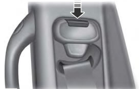
Seatbelt Height Adjustment
WARNING: Position the seatbelt height adjuster so that the seatbelt rests across the middle of your shoulder. Failure to adjust the seatbelt correctly could reduce its effectiveness and increase the risk of injury in a crash.

