Ford Explorer: Steering Column / Removal and Installation - Steering Column Telescopic Motor
Ford Explorer 2020-2025 Service Manual / Chassis / Steering System / Steering Column / Removal and Installation - Steering Column Telescopic Motor
Removal
NOTE: Removal steps in this procedure may contain installation details.
-
Remove the steering column.
Refer to: Steering Column (211-04 Steering Column, Removal and Installation).
-
IPTV Free Trial
NOTE: Note the position of the component before removal.
Remove the telescopic motor.
-
Remove the trunnion retainers.
-
Remove the telescopic motor retainers and remove the telescopic motor.
-
Remove the trunnion retainers.
.jpg) |
Installation
-
On both sides.
Apply grease (supplied with the new motor) to the trunnion nut axles and the telescopic motor lead-screw housing holes.
.jpg) |
-
Rotate the trunnion nut until the correct length is
achieved to align the lead-screw housing with the threaded holes in the
support arm.
.jpg) |
-
Install the telescopic motor.
-
Position the telescopic motor and install the telescopic motor retainers.
Torque: 124 lb.in (14 Nm)
-
Install the trunnion retainers.
Torque: 124 lb.in (14 Nm)
-
Position the telescopic motor and install the telescopic motor retainers.
.jpg) |
-
Install the steering column.
Refer to: Steering Column (211-04 Steering Column, Removal and Installation).
-
If equipped with memory steering column, use the
steering column control switch and set the telescopic motor soft stops
as follows.
-
Move the column outward until it reaches the end of travel.
-
Move the column in the same direction until it reaches the end of travel again.
-
Move the column inward until it reaches the end of travel.
-
Move the column in the same direction until it reaches the end of travel again.
-
Move the column outward until it reaches the end of travel.
 Removal and Installation - Steering Column
Special Tool(s) /
General Equipment
Flat Headed Screw Driver
Removal
NOTICE:
To prevent damage to the clockspring, make sure the front wheels are in the straight-ahead position...
 Removal and Installation - Steering Column Lower Shaft
Removal
NOTE:
Removal steps in this procedure may contain installation details.
NOTICE:
Do not allow the steering column to rotate while the
steering column shaft is disconnected or d..
Other information:
Ford Explorer 2020-2025 Service Manual: Removal and Installation - Brake Pedal and Bracket
Removal NOTE: Removal steps in this procedure may contain installation details. Remove the BCM. Refer to: Body Control Module (BCM) (419-10 Multifunction Electronic Modules, Removal and Installation). NOTICE: Do not service the brake pedal or brake booster without first removing the stoplamp switch...
Ford Explorer 2020-2025 Service Manual: Removal and Installation - Evaporator
Removal NOTICE: Use extreme care when releasing the tabs on the climate control housing, or the tabs can be easily damaged. NOTE: Removal steps in this procedure may contain installation details. Remove the climate control housing. Refer to: Climate Control Housing (412-00 Climate Control System - General Information, Removal and Installation)...
Categories
- Manuals Home
- 6th Generation Explorer Owners Manual
- 6th Generation Explorer Service Manual
- Interior Trim and Ornamentation
- Description and Operation - Identification Codes
- Description and Operation - Jacking and Lifting - Overview
- New on site
- Most important about car
Gauges
4 Inch Display
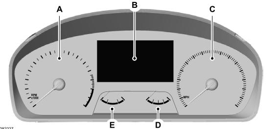
A - Tachometer.
B - Information display.
C - Speedometer.
D - Fuel gauge.
E - Engine coolant temperature gauge.
Copyright © 2025 www.foexplorer.com