Ford Explorer: Power Steering / Removal and Installation - Steering Gear Boot
Special Tool(s) / General Equipment
| Boot Clamp Pliers |
Materials
| Name | Specification |
|---|---|
| Motorcraft® Premium Long-Life Grease XG-1-E1 |
ESA-M1C75-B |
Removal
NOTICE: The steering gear boots and clamps are designed to provide an airtight seal and protect the internal components of the steering gear. If the seal is not airtight, the vacuum generated during turning will draw water and contamination into the gear, causing failure of the steering gear components. Zip ties must not be used as they do not provide an airtight seal.
NOTICE: The inner ball joint grease is not compatible with water contamination. Do not allow water to become trapped in the grease or degradation and failure of the joint may occur.
-
Remove the tie rod end.
Refer to: Tie Rod End (211-02 Power Steering, Removal and Installation).
-
Remove the tie rod end jamb nut.
.jpg) |
-
If equipped.
Remove the underbody shield.
Refer to: Engine Front Undershield (501-02 Front End Body Panels, Removal and Installation).
-
-
Remove and discard the inner bellows boot clamp.
-
Remove and discard the outer bellows boot clamp.
-
Remove and discard the inner bellows boot clamp.
.jpg) |
-
NOTE: Move the bellows boot enough to gain access to the inner tie rod nut.
Position aside the bellows boot.
.jpg) |
Installation
-
Apply the specified grease to the steering
gear-to-bellows boot mating surface and bellows boot groove on the
tie-rod.
Material: Motorcraft® Premium Long-Life Grease / XG-1-E1 (ESA-M1C75-B)
.jpg) |
-
-
Install the new steering gear bellows boot.
-
Install the new inner bellows boot clamp.
Use the General Equipment: Boot Clamp Pliers
-
Install the new outer bellows boot clamp.
-
Install the new steering gear bellows boot.
.jpg) |
-
If equipped.
Install the underbody shield.
Refer to: Engine Front Undershield (501-02 Front End Body Panels, Removal and Installation).
-
Thread the tie rod end jam nut onto the tie rod.
|
-
Install the tie rod end.
Refer to: Tie Rod End (211-02 Power Steering, Removal and Installation).
 Removal and Installation - Steering Gear
Special Tool(s) /
General Equipment
Tie Rod End Remover
Removal
NOTICE:
Suspension fasteners are critical parts that affect
performance of vital components and systems...
 Removal and Installation - Tie Rod
Special Tool(s) /
General Equipment
Boot Clamp Pliers
Materials
Name
Specification
Motorcraft® Premium Long-Life GreaseXG-1-E1
ESA-M1C75-B
Removal
NOTICE:
When ..
Other information:
Ford Explorer 2020-2025 Service Manual: Removal and Installation - Interior Rear View Mirror
Special Tool(s) / General Equipment 501-025Installer, Rear View Mirror 501-D118A (501-D118) Mirror Remover Removal NOTE: Removal steps in this procedure may contain installation details. Mirror Types Mirror type 1 Release the clips and remove the rain sensor cover...
Ford Explorer 2020-2025 Service Manual: Removal and Installation - High Voltage Battery Coolant Cover - Hybrid Electric Vehicle (HEV)
Special Tool(s) / General Equipment Locking Pliers Removal WARNING: To prevent the risk of high-voltage shock, always follow precisely all warnings and service instructions, including instructions to depower the system. The high-voltage system utilizes approximately 450 volts DC, provided through high-voltage cables to its components and modules...
Categories
- Manuals Home
- 6th Generation Explorer Owners Manual
- 6th Generation Explorer Service Manual
- Using Tether Straps
- Automatic Transmission - 10-Speed Automatic Transmission – 10R60
- General Procedures - Transmission Fluid Drain and Refill
- New on site
- Most important about car
Child Safety Locks
When these locks are set, you cannot open the rear doors from the inside.
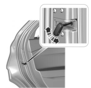
A child safety lock is on the rear edge of each rear door. You must set the child safety lock separately on each door.
Left-Hand Side