Ford Explorer: Rear Suspension / Removal and Installation - Wheel Bearing and Wheel Hub
Ford Explorer 2020-2026 Service Manual / Chassis / Suspension / Rear Suspension / Removal and Installation - Wheel Bearing and Wheel Hub
Special Tool(s) / General Equipment
.jpg) |
205-D070
(D93P-1175-B)
Remover, Front Wheel Hub |
Removal
NOTICE: Suspension fasteners are critical parts that affect the performance of vital components and systems. Failure of these fasteners may result in major service expense. Use the same or equivalent parts if replacement is necessary. Do not use a replacement part of lesser quality or substitute design. Tighten fasteners as specified.
-
Remove the wheel and tire.
Refer to: Wheel and Tire (204-04A Wheels and Tires, Removal and Installation).
-
Remove and discard the wheel hub nut.
.jpg) |
-
Install the special tool and press the halfshaft from the rear wheel bearing and wheel hub.
Use Special Service Tool: 205-D070 (D93P-1175-B) Remover, Front Wheel Hub.
.jpg) |
-
Remove the brake disc.
Refer to: Brake Disc (206-04 Rear Disc Brake, Removal and Installation).
-
Remove the lower arm vertical link.
Refer to: Lower Arm Vertical Link (204-02 Rear Suspension, Removal and Installation).
-
Remove and discard the wheel bearing and wheel hub retainers and remove the wheel bearing and wheel hub.
.jpg) |
Installation
-
NOTE: Tighten the bolts in a cross pattern.
Install the wheel bearing and wheel hub and install the new wheel bearing and wheel hub retainers.
Torque: 111 lb.ft (150 Nm)
.jpg) |
-
Install the lower arm vertical link.
Refer to: Lower Arm Vertical Link (204-02 Rear Suspension, Removal and Installation).
-
Install the brake disc.
Refer to: Brake Disc (206-04 Rear Disc Brake, Removal and Installation).
-
NOTE: Apply the brake to keep the halfshaft from rotating.
Install the new wheel hub nut.
Torque: 221 lb.ft (300 Nm)
.jpg) |
-
Install the wheel and tire.
Refer to: Wheel and Tire (204-04A Wheels and Tires, Removal and Installation).
 Removal and Installation - Upper Arm
Special Tool(s) /
General Equipment
Vehicle/Axle Stands
Removal
NOTICE:
Suspension fasteners are critical parts that affect the
performance of vital components and systems...
 Removal and Installation - Wheel Knuckle
Removal
NOTICE:
Suspension fasteners are critical parts that affect the
performance of vital components and systems. Failure of these fasteners
may result in major service expense...
Other information:
Ford Explorer 2020-2026 Service Manual: Removal and Installation - Liftgate Moulding
Removal NOTE: Removal steps in this procedure may contain installation details. Remove the liftgate trim panel. Refer to: Liftgate Trim Panel (501-05 Interior Trim and Ornamentation, Removal and Installation). Disconnect the washer hose and the electrical connector...
Ford Explorer 2020-2026 Service Manual: Removal and Installation - Front Lower Arm
Special Tool(s) / General Equipment 204-592Separator, Lower Arm Ball JointTKIT-2006C-FFMFLMTKIT-2006C-LMTKIT-2006C-ROW Vehicle/Axle Stands Removal NOTICE: Suspension fasteners are critical parts that affect the performance of vital components and systems...
Categories
- Manuals Home
- 6th Generation Explorer Owners Manual
- 6th Generation Explorer Service Manual
- Driveline
- General Procedures - Transmission Fluid Drain and Refill
- Description and Operation - Jacking and Lifting - Overview
- New on site
- Most important about car
Windshield Wipers
 Push the lever up or down to operate
the windshield wipers.
Push the lever up or down to operate
the windshield wipers.
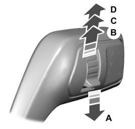
A - Single wipe.
Copyright © 2026 www.foexplorer.com