Ford Explorer: Body Repairs - General Information / Specifications
General Specifications
| Item | Specification |
|---|---|
| Plug Weld hole | 8 mm (0.315 in) |
| Weld Wire ER70S-3 | 0.9 mm (0.0354 in) - 1.1 mm (0.0433 in) |
| Weld Wire ER70S-6 | 0.9 mm (0.0354 in) - 1.1 mm (0.0433 in) |
IPTV Free Trial
Weld Nugget Chart
| Test Thickness of Metal | Nugget Size |
|---|---|
| 0.7 mm (0.0276 in) + 0.7 mm (0.0276 in) | 4.3 mm (0.1693 in) |
| 0.7 mm (0.0276 in) + 0.7 mm (0.0276 in) + 0.7 mm (0.0276 in) | 4.3 mm (0.1693 in) |
| 0.9 mm (0.0354 in) + 0.9 mm (0.0354 in) | 4.7 mm (0.185 in) |
| 0.9 mm (0.0354 in) + 0.9 mm (0.0354 in) + 0.9 mm (0.0354 in) | 4.7 mm (0.185 in) |
| 1 mm (0.0394 in) + 1 mm (0.0394 in) | 5.2 mm (0.2047 in) |
| 1 mm (0.0394 in) + 1 mm (0.0394 in) + 1 mm (0.0394 in) | 5.2 mm (0.2047 in) |
| 2 mm (0.0787 in) + 2 mm (0.0787 in) | 7.1 mm (0.2795 in) |
| 2 mm (0.0787 in) + 2 mm (0.0787 in) + 2 mm (0.0787 in) | 7.1 mm (0.2795 in) |
| 3 mm (0.1181 in) + 3 mm (0.1181 in) | 8.7 mm (0.3425 in) |
| 3 mm (0.1181 in) + 3 mm (0.1181 in) + 3 mm (0.1181 in) | 8.7 mm (0.3425 in) |
| 3 mm (0.1181 in) + 0.7 mm (0.0276 in) | 4.3 mm (0.1693 in) |
| 0.7 mm (0.0276 in) + 3 mm (0.1181 in) + 1 mm (0.0394 in) | 5.2 mm (0.2047 in) |
| 2 mm (0.0787 in) + 2 mm (0.0787 in) + 0.7 mm (0.0276 in) | 4.3 mm (0.1693 in) |
| 0.9 mm (0.0354 in) + 0.9 mm (0.0354 in) + 2 mm (0.0787 in) | 4.7 mm (0.185 in) |
| 2 mm (0.0787 in) + 0.9 mm (0.0354 in) + 1 mm (0.0394 in) | 5.2 mm (0.2047 in) |
| 1 mm (0.0394 in) + 3 mm (0.1181 in) + 1 mm (0.0394 in) | 5.2 mm (0.2047 in) |
| 3 mm (0.1181 in) + 1 mm (0.0394 in) + 2 mm (0.0787 in) | 7.1 mm (0.2795 in) |
| 0.9 mm (0.0354 in) + 0.7 mm (0.0276 in) + 0.9 mm (0.0354 in) | 4.3 mm (0.1693 in) |
Ford Recommended Steel Repairability Matrix
| Grade | Trade Descriptions | Welding Method | Cold Repairs | Use of Heat for Repair | Temperature Range | Maximum Heat | ||
|---|---|---|---|---|---|---|---|---|
| MIG | Squeeze-Type Resistance Spot Welding (STRW) | MIG Braze | ||||||
| Mild Steel | Mild | Yes | Yes | N/A | Yesa | Yes | Up to 650° C (1,200° F) | 90 seconds x 2 |
| Laminate Steel | Quiet Steel | No | Yes | No | Yesa | NA | NA | NA |
| Bake Hardened Steel (BH) | Bake Hardened Steel (BH) 180, 200, 210, 220, 250, 280 | Yes | Yes | Yesb | Yesa | Yes | Up to 650° C (1,200° F) | 90 seconds x 2 |
| Solid Solution Strengthened | - | Yes | Yes | Yesb | Yesa | Yes | Up to 650° C (1,200° F) | 90 seconds x 2 |
| High-Strength Low Alloy (HSLA) | High-Strength Low Alloy (HSLA) 200, High-Strength Low Alloy (HSLA 250, High-Strength Low Alloy (HSLA 260, High-Strength Low Alloy (HSLA 300, High-Strength Low Alloy (HSLA 340, High-Strength Low Alloy (HSLA 350, High-Strength Low Alloy (HSLA 500, High-Strength Low Alloy (HSLA) 550 | Yes | Yes | Yesb | Yesa | Yes | Up to 650° C (1,200° F) | 90 seconds x 2 |
| Dual Phase Steel (DP) | Dual Phase Steel (DP) 500, Dual Phase Steel (DP) 600 | Yes | Yes | Yesb | Yesa | No | NA | NA |
| Dual Phase Steel (DP)c | Dual Phase Steel (DP) 700, Dual Phase Steel (DP) 900 and Dual Phase Steel (DP) 1,000 | Yesd | Yes | Yesb | No | No | NA | NA |
| Ultra High Strength Steel (UHSS) (Martensitic, Boron)e | Boron, Martensitic | Yesa | Yes | Yesb | No | No | NA | NA |
| Transformation Induced Plasticity Steel (TRIP) | Transformation Induced Plasticity Steel (TRIP) 590, Transformation Induced Plasticity Steel (TRIP) 780, Transformation Induced Plasticity Steel (TRIP) 980 | NA | NA | NA | NA | NA | NA | NA |
aCold repairs can be performed if damage excludes kinks. May section only if approved procedure in workshop manual.
bMetal Inert Gas (MIG) braze allowed for non-structural applications only.
cDual phase steels DP 700 class, DP 900 class and DP 1,000 class must be replaced at factory joints, no sectioning unless approved procedure in workshop manual.
dFor DP 900, 1,000 and Boron use Metal Inert Gas (MIG) plug welding only, no stitch welding.
eBoron and Ultra High Strength Steel (UHSS)-Mortensite components must be replaced at factory joints, no sectioning allowed.

 Description and Operation - Complete Panel Replacement/Partial Replacement
Partial Replacement
Item
Description
1
Sectioning area
2
Manufacture weld joint
Decision Criteria
The following ..
Other information:
Ford Explorer 2020-2025 Service Manual: Removal and Installation - Front Seat Backrest Blower Motor
Special Tool(s) / General Equipment Interior Trim Remover Removal NOTE: Driver seat shown, passenger seat similar. Remove the front seat. Refer to: Front Seat (501-10A Front Seats, Removal and Installation). Release the front seat backrest panel straps...
Ford Explorer 2020-2025 Owners Manual: Instrument Panel
A - Air vents. B - Direction indicator. See Direction Indicators. C - Cruise control. See Cruise Control. Audio control. See Audio Control. D - Information display. See General Information. E - Information display control. See Information Display Control...
Categories
- Manuals Home
- 6th Generation Explorer Owners Manual
- 6th Generation Explorer Service Manual
- Auxiliary Power Points
- Interior Trim and Ornamentation
- Automatic Transmission - 10-Speed Automatic Transmission – 10R60
- New on site
- Most important about car
Gauges
4 Inch Display
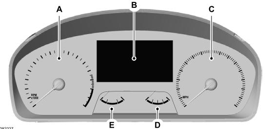
A - Tachometer.
B - Information display.
C - Speedometer.
D - Fuel gauge.
E - Engine coolant temperature gauge.