Ford Explorer: Automatic Transmission - 10-Speed Automatic Transmission – 10R60 / Description and Operation - Torque Converter
Overview
.jpg)
| Item | Description |
| 1 | TCC solenoid |
| 2 | TCC regulator valve assembly |
| 3 | TCC apply circuit |
| 4 | TCC release circuit |
Torque Converter Hydraulic Circuits (TCC Released)
.jpg)
| Item | Description |
| 1 | LPC pressure |
| 2 | TCC solenoid |
| 3 | TCC control pressure |
| 4 | TCC regulator valve |
| 5 | TCC release pressure |
| 6 | TCC |
| 7 | TCC exhaust to TCC regulator valve |
| 8 | Torque converter anti-drainback valve |
| 9 | TCC exhaust |
| 10 | Pump output |
| 11 | Decreased pressure from main requlator valve |
Line pressure fills the converter feed circuit with fluid up to 1,103 kPa (160 psi). The converter feed blow off valve prevents excessive pressure from reaching the torque converter. When the TCC solenoid is commanded off, the TCC regulator valve connects the converter feed circuit to the converter release circuit and fluid flows into the torque converter. Fluid exits the torque converter in the converter apply circuit. The TCC regulator valve connects the converter apply circuit and the from converter circuit. The from converter circuit flows past the converter anti-drainback valve and on to the cooler bypass valve.
Torque Converter Hydraulic Circuits (TCC Applied)
.jpg)
| Item | Description |
| 1 | Pump output |
| 2 | TCC solenoid |
| 3 | TCC control pressure |
| 4 | TCC regulator valve |
| 5 | LPC pressure |
| 6 | TCC apply pressure |
| 7 | TCC |
| 8 | TCC exhaust to TCC regulator valve |
| 9 | Torque converter anti-drainback valve |
| 10 | TCC exhaust |
| 11 | Decreased pressure from main requlator valve |
To apply to TCC, the TCC solenoid directs TCC control pressure to the TCC regulator valve, moving the valve to the left against the spring pressure. The TCC regulator valve is positioned to connect pump output to the converter apply circuit. Fluid in the apply circuit is routed to the converter and applies the TCC. Fluid exits the torque converter in the converter release circuit. The TCC regulator valve connects the converter release to exhaust and fluid returns to the sump.
When the TCC regulator valve is in the TCC applied position, the converter feed circuit is connected to the from converter circuit allowing continued fluid flow to the cooler bypass valve.
Torque Converter Hydraulic Passages (TCC Released)
.jpg)
.jpg)
.jpg)
Torque Converter Hydraulic Passages (TCC Applied)
.jpg)
.jpg)
.jpg)
 Description and Operation - Transmission Fluid Auxiliary Pump
Item
Description
1
Transmission fluid auxiliary pump
2
Transmission fluid auxiliary pump tube
3
Transmission fluid auxil..
 Diagnosis and Testing - Diagnostic Strategy
Overview
The
diagnostic process for each transmission concern will vary depending on
the symptoms and condition of the vehicle. The diagnostic process
below is an efficient method to collect as mu..
Other information:
Ford Explorer 2020-2025 Service Manual: Removal and Installation - Steering Wheel
Special Tool(s) / General Equipment Adhesive Tape Removal NOTE: Removal steps in this procedure may contain installation details. NOTE: Make sure the wheels and steering wheel is in the straight ahead position. NOTE: Vehicle without heated steering wheel shown others similar...
Ford Explorer 2020-2025 Service Manual: General Procedures - Piston Selection
Check NOTE: Refer to the appropriate Section 303-01 for the specifications. NOTE: The cylinder bore must be within the specifications for taper and out-of-round before fitting a piston. Measure the cylinder bore in 2 directions...
Categories
- Manuals Home
- 6th Generation Explorer Owners Manual
- 6th Generation Explorer Service Manual
- General Procedures - Rear Camber Adjustment
- Electric Parking Brake
- Description and Operation - Identification Codes
- New on site
- Most important about car
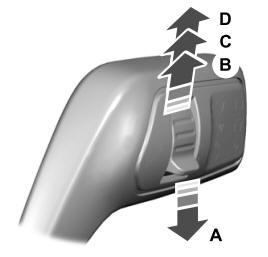
Windshield Wipers
 Push the lever up or down to operate
the windshield wipers.

A - Single wipe.
