Ford Explorer: Supplemental Restraint System / General Procedures - Clockspring Adjustment
Special Tool(s) / General Equipment
| Adhesive Tape |
.jpg) WARNING:
If the clockspring is not correctly centralized, it may fail
prematurely. If in doubt, repeat the centralizing procedure. Failure to
follow these instructions may increase the risk of serious personal
injury or death in a crash.
WARNING:
If the clockspring is not correctly centralized, it may fail
prematurely. If in doubt, repeat the centralizing procedure. Failure to
follow these instructions may increase the risk of serious personal
injury or death in a crash.
NOTE: Typical clockspring shown, others similar.
-
NOTICE: Do not over-rotate the clockspring rotor. The internal ribbon wire is connected to the clockspring rotor. The internal ribbon wire acts as a stop and can be broken from its internal connection. Failure to follow this instruction may result in component damage and/or system failure.
Turn the clockspring rotor clockwise, carefully feeling for resistance to turning.
.jpg) |
-
NOTE: The clockspring rotor must stop at the first instance that the electrical connector is at the 12 o'clock position.
Turn the clockspring rotor counterclockwise so the electrical connector is in the 12 o'clock position.
.jpg) |
-
NOTE: After final positioning, do not allow the clockspring rotor to rotate from this position.
Turn the clockspring rotor counterclockwise through 3 complete turns ending with the clockspring rotor electrical connector in the 12 o'clock position.
.jpg) |
-
When the clockspring is correctly centralized, the wiring
harness is visible through the site glass and the 2 arrows at the LH side are aligned. Make sure the clockspring does not rotate from this position until after the steering wheel is installed.
.jpg) |
-
Tape the clockspring inner rotor to the outer housing.
Use the General Equipment: Adhesive Tape
.jpg) |
 Diagnosis and Testing - Airbag Supplemental Restraint System (SRS)
Diagnostic Trouble Code (DTC) Chart
Diagnostics in this manual assume a certain skill level and knowledge of Ford-specific diagnostic practices. REFER to: Diagnostic Methods (100-00 General Informati..
 General Procedures - Inspection and Repair after a Supplemental Restraint System (SRS) Deployment
Inspection
NOTE:
Deployable devices such as airbags, pretensioners and
inflatable belt inflators, may deploy alone or in various combinations
depending on the impact event...
Other information:
Ford Explorer 2020-2025 Service Manual: Description and Operation - High Voltage Battery, Mounting and Cables - System Operation and Component Description
System Diagram Item Description 1 Current Sensor 2 Contactor Sense Leads 3 BECM 4 Precharge Contactor Coil 5 Positive Contactor Coil 6 Negative Contactor Coil 7 High Voltage Battery Junction Box 8 Temperature Sensors 9 Cell Voltage Sense Leads 10 PCM 11 Battery Cell Arrays 12 GWM 13 RCM ..
Ford Explorer 2020-2025 Service Manual: Removal and Installation - Battery Monitoring Sensor
Removal NOTE: When the battery is disconnected and connected, some abnormal drive symptoms may occur while the vehicle relearns its adaptive strategy. The vehicle may need to be driven to allow the PCM to relearn the adaptive strategy values. NOTE: Removal steps in this procedure may contain installation details...
Categories
- Manuals Home
- 6th Generation Explorer Owners Manual
- 6th Generation Explorer Service Manual
- General Procedures - Transmission Fluid Drain and Refill
- Engine - 2.3L EcoBoost (201kW/273PS)
- Removal and Installation - Liftgate Trim Panel
- New on site
- Most important about car
Gauges
4 Inch Display
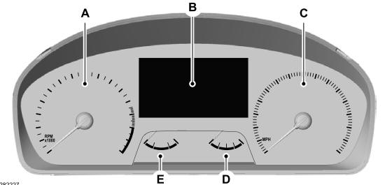
A - Tachometer.
B - Information display.
C - Speedometer.
D - Fuel gauge.
E - Engine coolant temperature gauge.