Ford Explorer: Engine Emission Control - 2.3L EcoBoost (201kW/273PS) / Removal and Installation - Crankcase Vent Oil Separator
Ford Explorer 2020-2025 Service Manual / Powertrain / Engine / Engine Emission Control - 2.3L EcoBoost (201kW/273PS) / Removal and Installation - Crankcase Vent Oil Separator
Removal
NOTE: Removal steps in this procedure may contain installation details.
-
Remove the intake manifold.
Refer to: Intake Manifold (303-01A) .
-
Disconnect the quick release coupling and remove the hose.
Refer to: Quick Release Coupling (310-00A Fuel System - General Information - 2.3L EcoBoost (201kW/273PS), General Procedures).
.jpg) |
-
Inspect the crankcase vent oil separator gasket.
.jpg) |
-
Remove the fasteners and crankcase vent oil separator.
.jpg) |
Installation
-
Install the crankcase vent oil separator and tighten in the sequence shown.
Torque: 97 lb.in (11 Nm)
.jpg) |
-
To install, reverse the removal procedure.
 Removal and Installation - Crankcase Ventilation Tube
Special Tool(s) /
General Equipment
Side Cutter Pliers
Materials
Name
Specification
Motorcraft® Silicone Brake Caliper Grease and Dielectric CompoundXG-3-A
ESE-M1C171-A
..
 Removal and Installation - Differential Pressure Feedback Exhaust Gas Recirculation (EGR) Sensor
Removal
NOTE:
Removal steps in this procedure may contain installation details.
Remove the bolt and position the coolant hose aside.
Torque:
97 lb...
Other information:
Ford Explorer 2020-2025 Service Manual: Removal and Installation - Roof Opening Panel Motor
Removal NOTE: Removal steps in this procedure may contain installation details. Lower the headliner. Refer to: Headliner - Lowering (501-05 Interior Trim and Ornamentation, Removal and Installation). Roof Opening Panel Motor - Glass NOTE: A new roof opening panel glass motor only moves toward the vent position until initialized...
Ford Explorer 2020-2025 Service Manual: Removal and Installation - Camshafts
Special Tool(s) / General Equipment 303-1685Alignment Tool, Camshaft 303-507Timing Peg, Crankshaft TDCTKIT-2001N-FLMTKIT-2001N-ROW Feeler Gauge Removal NOTE: During engine repair procedures, cleanliness is extremely important...
Categories
- Manuals Home
- 6th Generation Explorer Owners Manual
- 6th Generation Explorer Service Manual
- General Procedures - Brake Service Mode Activation and Deactivation
- Body and Paint
- Diagnosis and Testing - Parking Brake - Vehicles With: Electric Brake Booster
- New on site
- Most important about car
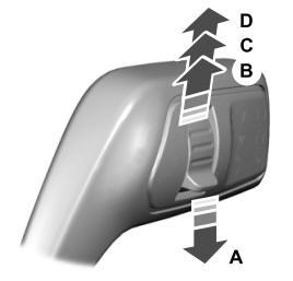
Windshield Wipers
 Push the lever up or down to operate
the windshield wipers.

A - Single wipe.
Copyright © 2025 www.foexplorer.com
