Ford Explorer: Engine - 2.3L EcoBoost (201kW/273PS) / Removal and Installation - Crankshaft Front Seal
Ford Explorer 2020-2026 Service Manual / Powertrain / Engine / Engine - 2.3L EcoBoost (201kW/273PS) / Removal and Installation - Crankshaft Front Seal
Special Tool(s) / General Equipment
.jpg) |
303-096
(T74P-6150-A)
Installer, Camshaft Front Oil Seal TKIT-2009TC-F |
.jpg) |
303-409
(T92C-6700-CH)
Remover, Crankshaft Seal TKIT-1992-FH/FMH/FLMH TKIT-1993-LMH/MH |
Removal
NOTICE: During engine repair procedures, cleanliness is extremely important. All parts must be thoroughly cleaned and any foreign material, including any material created while cleaning gasket surfaces, that enters the oil passages, coolant passages or the oil pan, can cause engine failure.
-
Remove the crankshaft pulley.
Refer to: Crankshaft Pulley (303-01A Engine - 2.3L EcoBoost (201kW/273PS), Removal and Installation).
-
Install the old crankshaft pulley bolt.
.jpg) |
-
NOTICE: Use care not to damage the engine front cover or the crankshaft when removing the seal.
Using the special tool, remove and discard the crankshaft front seal.
Use Special Service Tool: 303-409 (T92C-6700-CH) Remover, Crankshaft Seal.
.jpg) |
-
Remove and discard the crankshaft pulley bolt.
.jpg) |
Installation
-
-
Lubricate the crankshaft front seal with clean engine oil.
-
NOTE: Remove the through-bolt from the Camshaft Front Oil Seal Installer.
Using the special tool, install the crankshaft front seal.
Use Special Service Tool: 303-096 (T74P-6150-A) Installer, Camshaft Front Oil Seal.
-
Lubricate the crankshaft front seal with clean engine oil.
.jpg) |
-
Install the crankshaft pulley.
Refer to: Crankshaft Pulley (303-01A Engine - 2.3L EcoBoost (201kW/273PS), Removal and Installation).
 Removal and Installation - Camshafts
Special Tool(s) /
General Equipment
303-1685Alignment Tool, Camshaft
303-507Timing Peg, Crankshaft TDCTKIT-2001N-FLMTKIT-2001N-ROW
Feeler Gauge
Removal
NOTE:
During engin..
 Removal and Installation - Crankshaft Pulley
Special Tool(s) /
General Equipment
303-1521Alignment Tool, Crankshaft Position SensorTKIT-2010C-FLM
303-1686Holding Tool, Camshaft
303-1689Holding Tool, Crank Damper
303-5..
Other information:
Ford Explorer 2020-2026 Service Manual: Disassembly and Assembly of Subassemblies - Cylinder Head
Special Tool(s) / General Equipment 303-1249Valve Spring CompressorTKIT-2006UF-FLMTKIT-2006UF-ROW 303-1567Sizer, Teflon SealTKIT-2010C-FLM 303-300 (T87C-6565-A) Set, Valve Spring CompressorTKIT-1988-FESTIVAT88C-1000-STTKIT-1988-TRACERTKIT-2009TC-F 303-350 (T89P-6565-A) Compressor, Valve SpringTKIT-1990-LMHTKIT-1989-FTKIT-1989-FMTKIT-1989-FLM 303-472 (T94P-65..
Ford Explorer 2020-2026 Service Manual: Removal and Installation - Air Conditioning (A/C) Compressor - 2.3L EcoBoost (201kW/273PS)
Materials Name Specification Motorcraft® Silicone Brake Caliper Grease and Dielectric CompoundXG-3-A ESE-M1C171-A Removal NOTICE: If installing a new A/C compressor due to an internal failure of the old unit, carry out the following procedures to remove contamination from the A/C system...
Categories
- Manuals Home
- 6th Generation Explorer Owners Manual
- 6th Generation Explorer Service Manual
- Automatic Transmission
- Interior Trim and Ornamentation
- General Procedures - Transmission Fluid Drain and Refill
- New on site
- Most important about car
Child Safety Locks
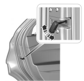
When these locks are set, you cannot open the rear doors from the inside.

A child safety lock is on the rear edge of each rear door. You must set the child safety lock separately on each door.
Left-Hand Side
Copyright © 2026 www.foexplorer.com
