Ford Explorer: Interior Trim and Ornamentation / Removal and Installation - Front Door Trim Panel
Ford Explorer 2020-2025 Service Manual / Body and Paint / Body and Paint / Interior Trim and Ornamentation / Removal and Installation - Front Door Trim Panel
Special Tool(s) / General Equipment
| Interior Trim Remover |
Removal
NOTE: LH (left hand) shown, RH (right hand) similar.
NOTE: Removal steps in this procedure may contain installation details.
-
Remove the interior front door handle bolt cover.
-
Position the interior front door handle aside.
-
Release the clips.
Use the General Equipment: Interior Trim Remover
-
Position the interior front door handle aside.
.jpg) |
-
Remove the interior front door handle bolt.
Torque: 48 lb.in (5.4 Nm)
.jpg) |
-
Remove the front door window control switch.
Refer to: Driver Door Window Control Switch (501-11 Glass, Frames and Mechanisms, Removal and Installation).
Refer to: Passenger Door Window Control Switch (501-11 Glass, Frames and Mechanisms, Removal and Installation).
-
Remove the front door trim panel middle bolt.
Torque: 48 lb.in (5.4 Nm)
.jpg) |
-
Remove the front door trim panel lower bolts.
Torque: 15 lb.in (1.7 Nm)
.jpg) |
-
Release the front door trim panel clips.
Use the General Equipment: Interior Trim Remover
.jpg) |
-
Remove the front door trim panel.
-
Lift upward and outward on the front door trim panel.
-
Release the tabs and position the door lock indicator aside.
-
Release the tab and position the interior front door cable aside.
-
If equipped.
Disconnect the front door ambient light electrical connector.
-
If equipped.
Disconnect the front door tweeter speaker electrical connector.
-
Disconnect the front door lock control switch electrical connector.
-
If equipped.
Disconnect the front door speaker electrical connector.
-
Lift upward and outward on the front door trim panel.
.jpg) |
Installation
-
To install, reverse the removal procedure.
 Removal and Installation - D-Pillar Trim Panel - Police
Special Tool(s) /
General Equipment
Interior Trim Remover
Removal
NOTE:
LH (left hand) shown, RH (right hand) similar.
Position the liftgate opening weatherstrip aside...
 Removal and Installation - Front Scuff Plate Trim Panel
Special Tool(s) /
General Equipment
Interior Trim Remover
Removal
NOTE:
LH (left hand) shown, RH (right hand) similar.
Left hand side
Remove the hood latch release handle...
Other information:
Ford Explorer 2020-2025 Service Manual: Removal and Installation - Side Obstacle Detection Control Module
Removal NOTE: LH side shown, RH side is similar. Remove the rear bumper cover. Refer to: Rear Bumper Cover (501-19 Bumpers, Removal and Installation). NOTE: This step is only necessary if the SODL or SODR is being replaced...
Ford Explorer 2020-2025 Service Manual: Removal and Installation - Transmission Fluid Pump Idler Gear
Special Tool(s) / General Equipment 205-1018Installation Tube 307-003 (T57L-500-B) Holding Fixture, Transmission 307-091Handle, Torque ConverterTKIT-2009TC-F 307-346 (T97T-7902-A) Retainer, Torque ConverterTKIT-1998-LM (NavigatoR)TKIT-1997-F/FLM/LT 307-736Installer, Pump Drive Gear Bearing 307-737Press Tool, Oil Pump Drive Idler Gear 307-743Remo..
Categories
- Manuals Home
- 6th Generation Explorer Owners Manual
- 6th Generation Explorer Service Manual
- Removal and Installation - All-Wheel Drive (AWD) Module
- General Procedures - Rear Camber Adjustment
- General Procedures - Transmission Fluid Drain and Refill
- New on site
- Most important about car
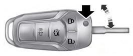
Integrated Keyhead Transmitter (If Equipped)
Use the key blade to start your vehicle and unlock or lock the driver door from outside your vehicle. The integrated keyhead transmitter functions as a programmed ignition key that operates all the locks and starts your vehicle, as well as a remote control.
Copyright © 2025 www.foexplorer.com