Ford Explorer: Front Seats / Removal and Installation - Front Seat Control Switch
Ford Explorer 2020-2025 Service Manual / Body and Paint / Body and Paint / Front Seats / Removal and Installation - Front Seat Control Switch
Removal
NOTE: Driver seat control switch shown, all others similar.
-
Remove the front seat.
Refer to: Front Seat (501-10A Front Seats, Removal and Installation).
-
If equipped with manual recline.
Remove the front seat recline handle cover.
-
Lift the recline handle.
-
Remove the screw.
-
Remove the recline handle cover.
-
Lift the recline handle.
.jpg) |
-
Remove the side shield screw.
.jpg) |
-
-
Lift up and out, separating the side shield from the recliner bracket.
-
Slide the side shield forward and separate the side shield from the seat.
-
Lift up and out, separating the side shield from the recliner bracket.
.jpg) |
-
Disconnect the front seat control switch electrical connector and remove the side shield.
.jpg) |
-
Remove the front seat control switch knob(s).
.jpg) |
-
Remove the screws and the front seat control switch.
.jpg) |
Installation
-
To install, reverse the removal procedure.
 Removal and Installation - Front Seat Backrest Cover
Removal
WARNING:
Front seat backrest trim covers installed on seats equipped
with seat side airbags cannot be repaired. A new trim cover must be
installed...
 Removal and Installation - Front Seat Cushion Adjuster - Vehicles With: Multi-Contour Seats
Special Tool(s) /
General Equipment
Interior Trim Remover
Removal
NOTE:
Driver seat shown, passenger seat similar.
Remove the front seat...
Other information:
Ford Explorer 2020-2025 Service Manual: Description and Operation - Engine - Overview
Engine Information NOTE: When repairing engines, all parts must be contamination free. If contamination/foreign material is present when repairing an engine, premature engine failure may occur. NOTE: Specifications show the expected minimum or maximum condition...
Ford Explorer 2020-2025 Service Manual: Specifications
General Specifications Item Specification 2.3L EcoBoost - Limited and XLT with trailer tow vehicles built before October 2020 Rating 220 amps Generator amps at 80.6°F (27°C) 117...
Categories
- Manuals Home
- 6th Generation Explorer Owners Manual
- 6th Generation Explorer Service Manual
- General Procedures - Transmission Fluid Drain and Refill
- Body and Paint
- Interior Trim and Ornamentation
- New on site
- Most important about car
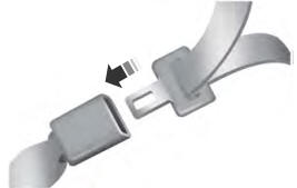
Fastening the Seatbelts
The front outboard and rear safety restraints in the vehicle are combination lap and shoulder belts.
Copyright © 2025 www.foexplorer.com