Ford Explorer: Exterior Lighting / Removal and Installation - Headlamp Leveling Sensor
Ford Explorer 2020-2025 Service Manual / Electrical / Lighting / Exterior Lighting / Removal and Installation - Headlamp Leveling Sensor
Removal
NOTE: Removal steps in this procedure may contain installation details.
Front suspension mounted
-
Remove the LH front wheel and tire assembly.
Refer to: Wheel and Tire (204-04A Wheels and Tires, Removal and Installation).
-
Disconnect the front ride height sensor electrical connector.
.jpg) |
-
Remove the front headlamp leveling sensor.
-
Remove the front headlamp leveling sensor arm anchor plate bolt.
Torque: 93 lb.in (10.5 Nm)
-
Remove the front headlamp leveling sensor anchor plate bolt.
Torque: 177 lb.in (20 Nm)
-
Remove the front headlamp leveling sensor assembly.
-
Remove the front headlamp leveling sensor arm anchor plate bolt.
.jpg) |
Rear suspension mounted
-
Remove the LH rear wheel and tire assembly.
Refer to: Wheel and Tire (204-04A Wheels and Tires, Removal and Installation).
-
Disconnect the rear ride height sensor electrical connector and separate the wiring harness guide.
.jpg) |
-
Lower the rear headlamp leveling sensor arm anchor plate.
-
Remove the rear headlamp leveling sensor anchor plate bolt.
Torque: 22 lb.ft (30 Nm)
-
Remove the rear headlamp leveling sensor arm anchor plate bolt.
Torque: 133 lb.in (15 Nm)
-
Remove the rear headlamp leveling sensor assembly.
-
Remove the rear headlamp leveling sensor anchor plate bolt.
.jpg) |
Installation
-
To install, reverse the removal procedure.
-
Calibrate the suspension height sensor. Using a
diagnostic scan tool, carry out the Ride Height Calibration routine.
Follow the scan tool directions.
 Removal and Installation - Headlamp Control Module (HCM)
Removal
NOTE:
This step is only necessary if the HCM is being replaced.
NOTE:
If installing a new module, it is necessary to
upload the module configuration information to the scan tool..
 Removal and Installation - Headlamp Switch
Special Tool(s) /
General Equipment
Interior Trim Remover
Removal
NOTE:
Removal steps in this procedure may contain installation details...
Other information:
Ford Explorer 2020-2025 Service Manual: Removal and Installation - Rear Shock Absorber
Special Tool(s) / General Equipment Vehicle/Axle Stands Removal NOTICE: Suspension fasteners are critical parts that affect the performance of vital components and systems. Failure of these fasteners may result in major service expense...
Ford Explorer 2020-2025 Owners Manual: Fuse Specification Chart
Engine Compartment Fuse Box WARNING: Always disconnect the battery before servicing high current fuses. WARNING: To reduce risk of electrical shock, always replace the cover to the power distribution box before reconnecting the battery or refilling fluid reservoirs...
Categories
- Manuals Home
- 6th Generation Explorer Owners Manual
- 6th Generation Explorer Service Manual
- Removal and Installation - Liftgate Trim Panel
- Removal and Installation - Front Halfshaft Speed Sensor
- Engine
- New on site
- Most important about car
Gauges
4 Inch Display
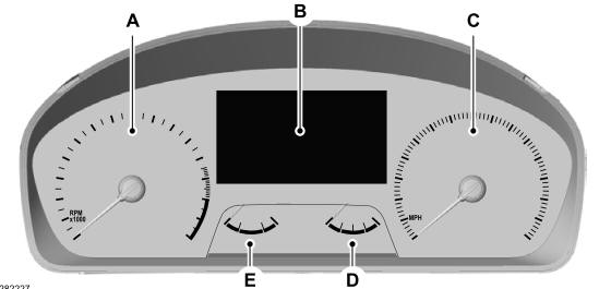
A - Tachometer.
B - Information display.
C - Speedometer.
D - Fuel gauge.
E - Engine coolant temperature gauge.
Copyright © 2025 www.foexplorer.com