Ford Explorer: Supplemental Restraint System / Removal and Installation - Passenger Airbag
Removal
.jpg) WARNING:
The following procedure prescribes critical repair steps
required for correct supplemental restraint system operation during a
crash. Follow all notes and steps carefully. Failure to follow step
instructions may result in incorrect operation of the supplemental
restraint system and increases the risk of serious personal injury or
death in a crash.
WARNING:
The following procedure prescribes critical repair steps
required for correct supplemental restraint system operation during a
crash. Follow all notes and steps carefully. Failure to follow step
instructions may result in incorrect operation of the supplemental
restraint system and increases the risk of serious personal injury or
death in a crash.
NOTE: Passenger airbag with canister vent shown, without canister vent similar.
-
Refer to: Pyrotechnic Device Health and Safety Precautions (100-00 General Information, Description and Operation)..jpg) WARNING:
Before beginning any service procedure in this
manual, refer to health and safety warnings in section 100-00 General
Information. Failure to follow this instruction may result in serious
personal injury.
WARNING:
Before beginning any service procedure in this
manual, refer to health and safety warnings in section 100-00 General
Information. Failure to follow this instruction may result in serious
personal injury.
-
Depower the SRS.
Refer to: Supplemental Restraint System (SRS) Depowering (501-20B Supplemental Restraint System, General Procedures).
-
Remove the instrument panel upper section.
Refer to: Instrument Panel Upper Section (501-12 Instrument Panel and Console, Removal and Installation).
-
NOTE: This step is only necessary when installing a new passenger airbag.
Remove the screw and bracket.
.jpg) |
-
Remove the screws and brackets.
.jpg) |
-
-
Pull the passenger airbag deployment chute away from the passenger airbag.
-
Rotate the passenger airbag out of the deployment chute and disengage the passenger airbag retainers.
-
Pull the passenger airbag deployment chute away from the passenger airbag.
.jpg) |
-
Continue to rotate the passenger airbag and remove it from the deployment chute.
.jpg) |
Installation
.jpg) WARNING:
Incorrect repair techniques or actions can cause an
accidental Supplemental Restraint System deployment. Make sure the
restraint system is depowered before reconnecting the component. Refer
to the Supplemental Restraint System depowering General Procedure in
section 501-20B. Failure to precisely follow depowering instructions
could result in serious personal injury from an accidental deployment.
WARNING:
Incorrect repair techniques or actions can cause an
accidental Supplemental Restraint System deployment. Make sure the
restraint system is depowered before reconnecting the component. Refer
to the Supplemental Restraint System depowering General Procedure in
section 501-20B. Failure to precisely follow depowering instructions
could result in serious personal injury from an accidental deployment.
-
.jpg) WARNING:
Before installing the passenger air bag module assembly:
WARNING:
Before installing the passenger air bag module assembly:
- Inspect the passenger air bag module and instrument panel/deployment chute cavity for any damage or foreign material.
- Remove any foreign material from the passenger air bag module and instrument panel/deployment chute cavity.
- Install new parts if damaged.
-
Position the passenger airbag to the deployment chute.
-
Engage the passenger airbag retainers to the deployment chute.
.jpg) |
-
-
Pull the passenger airbag deployment chute out, making room for the passenger airbag to pass.
-
Rotate the passenger airbag down and into the deployment chute.
-
Pull the passenger airbag deployment chute out, making room for the passenger airbag to pass.
.jpg) |
-
Engage the passenger airbag retainers to the deployment chute.
.jpg) |
-
Install the brackets and screws.
Torque: 42 lb.in (4.8 Nm)
.jpg) |
-
Position the bracket and install the screw.
Torque: 42 lb.in (4.8 Nm)
.jpg) |
-
Install the instrument panel upper section.
Refer to: Instrument Panel Upper Section (501-12 Instrument Panel and Console, Removal and Installation).
-
Repower the SRS.
Refer to: Supplemental Restraint System (SRS) Repowering (501-20B Supplemental Restraint System, General Procedures).
 Removal and Installation - Occupant Classification System (OCS) Sensor - Vehicles Without: Multi-Contour Seats
Special Tool(s) /
General Equipment
Flat Headed Screw Driver
Removal
WARNING:
The following procedure prescribes critical repair steps
required for correct restraint system ope..
 Removal and Installation - Passenger Knee Airbag
Removal
WARNING:
The following procedure prescribes critical repair steps
required for correct restraint system operation during a crash. Follow
all notes and steps carefully...
Other information:
Ford Explorer 2020-2025 Owners Manual: Using Snow Chains
WARNING: Do not exceed 30 mph (50 km/h). Failure to follow this instruction could result in the loss of control of your vehicle, personal injury or death. WARNING: Do not use snow chains on snow-free roads. WARNING: Only fit snow chains to specified tires...
Ford Explorer 2020-2025 Service Manual: Removal and Installation - Tie Rod
Special Tool(s) / General Equipment Boot Clamp Pliers Materials Name Specification Motorcraft® Premium Long-Life GreaseXG-1-E1 ESA-M1C75-B Removal NOTICE: When servicing inner tie rods, install a new bellows boot and clamps...
Categories
- Manuals Home
- 6th Generation Explorer Owners Manual
- 6th Generation Explorer Service Manual
- Engine - 2.3L EcoBoost (201kW/273PS)
- General Procedures - Rear Camber Adjustment
- Removal and Installation - Front Halfshaft Speed Sensor
- New on site
- Most important about car
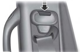
Seatbelt Height Adjustment
WARNING: Position the seatbelt height adjuster so that the seatbelt rests across the middle of your shoulder. Failure to adjust the seatbelt correctly could reduce its effectiveness and increase the risk of injury in a crash.

