Ford Explorer: Automatic Transmission - 10-Speed Automatic Transmission – 10R60 / Removal and Installation - Transmission Range (TR) Sensor
Special Tool(s) /
General Equipment
.jpg) |
307-783
Installer, Roll Pin |
| Rubber Mallet |
| Punch |
Materials
| Name |
Specification |
Motorcraft® MERCON® ULV Automatic Transmission Fluid
XT-12-QULV |
WSS-M2C949-A,
MERCON® ULV
|
Removal
-
Remove the main control valve body.
Refer to: Main Control Valve Body (307-01A Automatic Transmission - 10-Speed Automatic Transmission – 10R60, Removal and Installation).
-
Disconnect the TR sensor electrical connector and position the transmission wiring harness aside.
-
Remove the bolt, nuts and position aside the transmission fluid cooler.
-
Disconnect the manual park overide lever.
-
Remove the nut and the manual park overide lever.
-
Using a punch, remove and discard the manual shaft-to-TR sensor roll pin (7G100).
Use the General Equipment: Punch
-
Loosen the detent spring bolt and the detent spring enough to remove the tension from the TR sensor.
-
Release the tension from the park return spring.
-
Slide the end of the park return spring off the transmission case.
-
Remove the manual shaft from the TR sensor.
-
Remove the TR sensor (7H557).
-
Rotate the TR sensor.
-
Disconnect the park pawl actuator rod and remove the TR sensor.
Installation
-
Install the TR sensor.
-
Connect the park pawl actuator rod to the TR sensor.
-
Rotate the TR sensor.
-
Position the park pawl actuator rod into the park pawl sleeve.
-
Align the TR sensor to the detent spring.
-
Slide the manual shaft into the TR sensor.
-
Using the dimpled end of the special tool, install the new manual shaft-to-TR sensor roll pin flush with the shaft.
-
New roll pin
-
Dimpled end of special tool
Use Special Service Tool: 307-783
Installer, Roll Pin.
Use the General Equipment: Rubber Mallet
-
-
Align the detent spring in the center of the TR sensor.
-
Torque:
97 lb.in (11 Nm)
-
Slide the end of the park return spring onto the transmission case.
-
Install the manual park overide lever and nut.
Torque:
106 lb.in (12 Nm)
-
Connect the manual park overide lever.
-
Inspect the transmission fluid cooler O-ring seals and
install new O-ring seals if necessary. Lubricate the O-ring seals.
Material: Motorcraft® MERCON® ULV Automatic Transmission Fluid
/ XT-12-QULV
(WSS-M2C949-A, )
(MERCON® ULV)
-
NOTICE:
Make sure the oil cooler is completely installed
against the transmission before tightening, or damage to the cooler
could result.
Install the transmission fluid cooler and loosely install the bolt and the nuts by hand.
-
NOTICE:
Make sure the oil cooler is completely installed
against the transmission before tightening, or damage to the cooler
could result.
Tighten the bolt and nuts in the sequence shown.
Torque:
18 lb.ft (25 Nm)
-
Connect the TR sensor electrical connector.
-
Install the main control valve body.
Refer to: Main Control Valve Body (307-01A Automatic Transmission - 10-Speed Automatic Transmission – 10R60, Removal and Installation).
Special Tool(s) /
General Equipment
307-625Fixture, Bench MountingTKIT-2008ET-FLMTKIT-2008ET-ROW
307-746Remover, Transmission Wiring Harness Connector
Transmission Jack
Vehicle..
Special Tool(s) /
General Equipment
Transmission Jack
Wooden Block
Removal
With the vehicle in NEUTRAL, position it on a hoist...
Other information:
Special Tool(s) /
General Equipment
Air Conditioning Service Unit
Electronic Leak Detector
Air Conditioning Adaptor Kit
Leak detection
Recover the refrigerant. Refer to Air Conditioning (A/C)
System Recovery, Evacuation and Charging procedure in Group 412...
Special Tool(s) /
General Equipment
Feeler Gauge
Cleaning
Clean the exhaust manifold using a suitable solvent. Use
a plastic scraping tool to clean the gasket sealing surfaces.
Inspection
NOTE:
New exhaust manifold gaskets, studs, nuts and/or
bolts must be installed when an exhaust manifold is serviced...
Categories
4 Inch Display
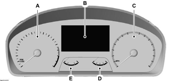
A - Tachometer.
B - Information display.
C - Speedometer.
D - Fuel gauge.
E - Engine coolant temperature gauge.
read more
.jpg)
.jpg)
.jpg)
.jpg)
.jpg)
.jpg)
.jpg)
.jpg)
.jpg)
.jpg)
.jpg)
.jpg)
.jpg)
.jpg)
.jpg)
.jpg)
 Removal and Installation - Transmission Internal Wiring Harness
 Removal and Installation - Transmission Support Insulator