Ford Explorer: Exhaust System - 2.3L EcoBoost (201kW/273PS) / Description and Operation - Exhaust System - Overview
Overview
NOTICE: Do not use leaded fuel in a vehicle equipped with a catalytic converter. In a vehicle that is continually misfueled, the lead in the fuel will be deposited in the catalytic converter and completely blanket the catalyst. Lead reacts with platinum to "poison" the catalyst. Continuous use of leaded fuel can destroy the catalyst and render the catalytic converter useless. The addition of lead to the catalytic converter can also solidify the catalyst, causing excessive back pressure in the exhaust system and possibly causing engine damage.
Apostilling, authenticating, Texas apostille. . IPTV Free TrialNOTICE: Extremely high temperatures of 1,100°C (2,012°F) or above due to misfiring or an over-rich fuel/air mixture will cause the ceramic substrate to sinter or burn, destroying the catalytic converter. Do not continue to operate the vehicle if the engine is misfiring, there is a power loss or other unusual operating conditions, such as engine overheating and backfiring.
NOTICE: Do not use oil or grease-based lubricants on the isolators. These lubricants may cause deterioration of the rubber. This can lead to separation of the isolator from the exhaust hanger bracket during vehicle operation.
The exhaust system provides an exit for exhaust gases and reduces engine noise by passing exhaust gases through the catalytic converters and a muffler assembly. The catalytic converters also play a major role in reducing air pollutants.
- a catalytic conveter assembly
- a muffler inlet pipe with exhaust flexible pipe
- a central resonator assembly
- two rear mufflers
- isolators between the the muffler and tailpipe assemblies and the vehicle body
The catalytic converter plays a major role in the emission control system by operating as a gas reactor. Its function is to speed the heat-producing chemical reaction of components in the exhaust gases to reduce air pollutants.
The catalyst material inside the catalytic converter consists of a ceramic substrate.
The catalytic converter is designed to provide a long life. No maintenance is necessary.
Sound insulators and shields, attached to the underbody, protect the vehicle from exhaust system heat and should be inspected at regular intervals to make sure they are not dented or out of position. If a sound insulator and shield is damaged or shows evidence of deterioration, install a new insulator and shield. The sound insulators and shields for the muffler, muffler pipe and catalytic converter pipe are installed separately.
Some exhaust fasteners must be discarded and new ones installed as indicated in the procedures. Discard any damaged or heavily corroded fasteners and install new ones as necessary. Some exhaust fasteners are of a prevailing torque design. Use only new fasteners with the same part number as the original. Tighten the fasteners to the specified torque during reassembly to make sure of correct retention of exhaust components.
 Diagnosis and Testing - Exhaust System
Symptom Chart(s)
Symptom Chart: Symptom Chart - Exhaust System
Verify
the customer concern. Inspect the components of the exhaust system for
obvious signs of damage or other mechanical concern..
Other information:
Ford Explorer 2020-2025 Service Manual: Disassembly and Assembly - Front Bumper Cover
Special Tool(s) / General Equipment Hot Air Gun DISASSEMBLY Remove the front bumper cover. Refer to: Front Bumper Cover (501-19 Bumpers, Removal and Installation). Disconnect the front bumper cover wiring harness connectors...
Ford Explorer 2020-2025 Owners Manual: Personal Safety System™
This system provides an improved overall level of frontal crash protection to front seat occupants and is designed to help further reduce the risk of airbag-related injuries. The system analyzes different occupant conditions and crash severity before activating the appropriate safety devices to help better protect occupants in a variety of frontal crash situations...
Categories
- Manuals Home
- 6th Generation Explorer Owners Manual
- 6th Generation Explorer Service Manual
- Fuel Filler Funnel Location & Running Out of Fuel
- Engine - 2.3L EcoBoost (201kW/273PS)
- Interior Trim and Ornamentation
- New on site
- Most important about car
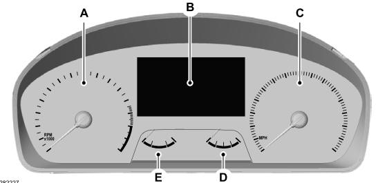
Gauges
4 Inch Display

A - Tachometer.
B - Information display.
C - Speedometer.
D - Fuel gauge.
E - Engine coolant temperature gauge.

