Ford Explorer: Multifunction Electronic Modules / Removal and Installation - Body Control Module (BCM)
Removal
NOTE: Removal steps in this procedure may contain installation details.
-
If installing a new BCM, connect a battery charger to the battery to make sure it is charged to maintain proper battery voltage.
Refer to: Battery Charging (414-01 Battery, Mounting and Cables, General Procedures).
-
https://magicaliptv.com/iptv-free-trials/
NOTE: Before replacing the BCM (body control module), ensure that two correct keys are present as they will be needed to complete the PMI (programmable module installation) with the FDRS scan tool. The vehicle will not start unless two keys are present.
NOTE: If the BCM did not respond to the diagnostic scan tool, As-Built Data may need to be entered as part of the repair. This step is only necessary if the BCM is being replaced.
Using a diagnostic scan tool, begin the PMI process for the BCM following the on-screen instructions.
Refer to: Module Configuration - System Operation and Component Description (418-01 Module Configuration, Description and Operation).
-
NOTE: The PAM is integral to the BCM. This step is only necessary if the BCM is being replaced.
Using a diagnostic scan tool, begin the PMI process for the PAM following the on-screen instructions.
Refer to: Module Configuration - System Operation and Component Description (418-01 Module Configuration, Description and Operation).
-
Release the pushpin and remove the drivers side insulation panel.
-
Remove the bolts.
-
Remove the nut.
-
Disconnect the electrical connector.
-
Remove the bolts.
.jpg) |
-
Remove the fuse access cover.
.jpg) |
-
Remove the bolts, release the clips and remove the lower steering column trim panel.
-
Release the tabs and position aside the electrical connector and harness.
-
Release the tabs and position aside the electrical connector and harness.
.jpg) |
-
NOTE: The gateway module is mounted to the bottom back side of the BCM.
Remove the nuts and position aside the gateway module.
.jpg) |
-
Disconnect the electrical connectors.
-
Remove the screw and the BCM.
-
Remove the screw and the BCM.
.jpg) |
Installation
-
To install, reverse the removal procedure.
NOTE: Carry out the remaining steps only if installing a new BCM.
-
NOTE: The PMI (programmable module installation) application in the scan tool will guide you through completing the BCM (body control module) programming and key programming.
Run the PMI on the BCM.
-
After keys have been programmed as directed by the on screen prompts, and the BCM programming has fully completed (as indicated by a module installation complete or successful message), carry out the PATS Module Initialization using the FDRS Scan Tool PATS Application.
-
As directed by the scan tool, follow the onscreen promts to relearn the TPMS sensors.
Refer to: Tire Pressure Monitoring System (TPMS) Sensor Location Calibration (204-04B Tire Pressure Monitoring System (TPMS), General Procedures).
-
If equipped with a video rear parking aid (rear mounted only), using a diagnostic scan tool, carry out the LIN New Module Initialization function.
-
Using a diagnostic scan tool, carry out the BMS Learned Values Reset.
-
Configure the BCM Programmable Parameters.
Refer to: Module Programming (418-01 Module Configuration, General Procedures).
-
Using a diagnostic scan tool, carry out the BCM self-test (must include an on-demand self-test) and then repeat the self-test to confirm all DTC have been cleared.
-
NOTE: This step only applies to vehicles without a stand-alone PAM (parking assist control module).
Using a diagnostic scan tool, complete the PMI process for the PAM following the on-screen instructions.
Refer to: Module Configuration - System Operation and Component Description (418-01 Module Configuration, Description and Operation).
 General Procedures - Transport Mode Deactivation
Deactivation
NOTE:
After vehicle build, some vehicle modules are set in Transport mode including the IPC and the BCM. Transport mode reduces battery drain during longer periods where the vehicle is..
 Removal and Installation - Body Control Module C (BCMC)
Removal
NOTE:
Removal steps in this procedure may contain installation details.
NOTE:
If the BCMC
did not respond to the diagnostic scan tool, As-Built Data may need to
be entered as p..
Other information:
Ford Explorer 2020-2025 Owners Manual: Hands-Free Feature (If Equipped)
Make sure you have the intelligent access remote within 3 ft (1 m) of the liftgate. Stand behind your vehicle, and face the liftgate. Move your foot, in a single-kick motion, without pausing, under and away from the rear bumper detection area...
Ford Explorer 2020-2025 Service Manual: Removal and Installation - Cabin Heater Coolant Diverter Valve
Special Tool(s) / General Equipment Hose Clamp(s) Hose Clamp Remover/Installer Removal NOTE: Removal steps in this procedure may contain installation details. Drain the cooling system. Refer to: Engine Cooling System Draining, Vacuum Filling and Bleeding (303-03D Engine Cooling - 3...
Categories
- Manuals Home
- 6th Generation Explorer Owners Manual
- 6th Generation Explorer Service Manual
- Auxiliary Power Points
- General Procedures - Rear Camber Adjustment
- Diagnosis and Testing - Parking Brake - Vehicles With: Electric Brake Booster
- New on site
- Most important about car
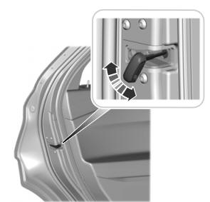
Child Safety Locks
When these locks are set, you cannot open the rear doors from the inside.

A child safety lock is on the rear edge of each rear door. You must set the child safety lock separately on each door.
Left-Hand Side
