Ford Explorer: Steering Column / Removal and Installation - Steering Column Opening Seal
Ford Explorer 2020-2025 Service Manual / Chassis / Steering System / Steering Column / Removal and Installation - Steering Column Opening Seal
Removal
NOTE: Removal steps in this procedure may contain installation details.
-
Remove the steering column upper shaft.
Refer to: Steering Column Upper Shaft (211-04 Steering Column, Removal and Installation).
-
Remove the cowl panel.
Refer to: Cowl Panel (501-02 Front End Body Panels, Removal and Installation).
NOTE: Note the position of the components before removal.
-
Push the cone into the rubber boot.
.jpg) |
-
Move the rubber boot aside to gain access to the steering column opening seal retainers.
.jpg) |
-
NOTE: Use a 1/4 inch drive wobble extension.
Remove the steering column opening seal retainers.
Torque: 106 lb.in (12 Nm)
.jpg) |
-
-
Remove the rubber boot.
-
Remove the steering column opening seal.
-
Remove the rubber boot.
.jpg) |
Installation
-
To install, reverse the removal procedure.
 Removal and Installation - Steering Column Lower Shaft
Removal
NOTE:
Removal steps in this procedure may contain installation details.
NOTICE:
Do not allow the steering column to rotate while the
steering column shaft is disconnected or d..
 Removal and Installation - Steering Column Upper Shaft
Removal
NOTE:
Removal steps in this procedure may contain installation details.
Remove the steering column.
Refer to: Steering Column (211-04 Steering Column, Removal and Installation)...
Other information:
Ford Explorer 2020-2025 Service Manual: General Procedures - Transmission Strategy Download
Programming This procedure should be performed when a new transmission or main control valve body is installed in the vehicle. 13 - digit solenoid body strategy 12 - digit solenoid body identification If a new main control was installed, record the 13-digit solenoid body strategy from the replacement solenoid body tag provided with the main control service kit...
Ford Explorer 2020-2025 Service Manual: Specifications
Lubricants, Fluids, Sealers and Adhesives NOTICE: Do not over-lubricate the driveshaft components. Using excessive grease may damage the driveshaft components. NOTE: Wipe off any excess grease. Item Description Specification Rear driveshaft: Front tube plunging splines Material: Motorcraft® Premium Long-Life Grea..
Categories
- Manuals Home
- 6th Generation Explorer Owners Manual
- 6th Generation Explorer Service Manual
- Description and Operation - Jacking and Lifting - Overview
- Removal and Installation - Front Halfshaft Speed Sensor
- Engine - 2.3L EcoBoost (201kW/273PS)
- New on site
- Most important about car
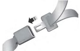
Fastening the Seatbelts
The front outboard and rear safety restraints in the vehicle are combination lap and shoulder belts.

Copyright © 2025 www.foexplorer.com
